¶ Tools and Materials
-
A 2.0 mm Allen key
-
A 2.5 mm Allen key
-
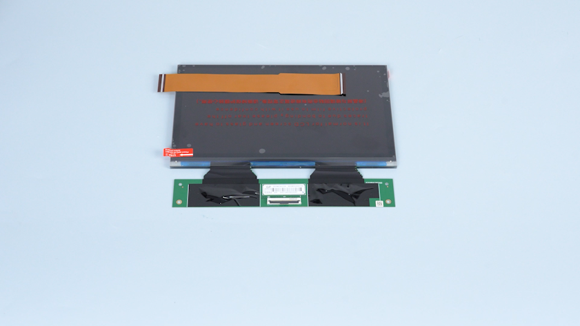
A new LCD screen
-
A new ribbon cable, tape and cable ties
¶ Instruction
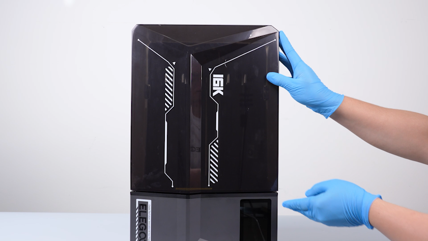
¶ Preparation
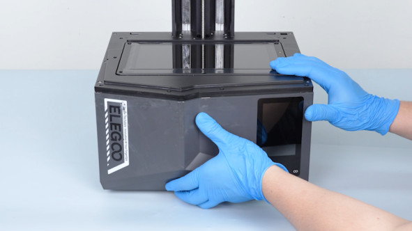
Turn the power switch OFF (symbol "〇"). Unplug the power adapter cable.
¶ Remove the old LCD screen
-
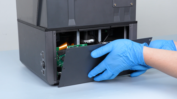
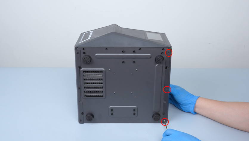
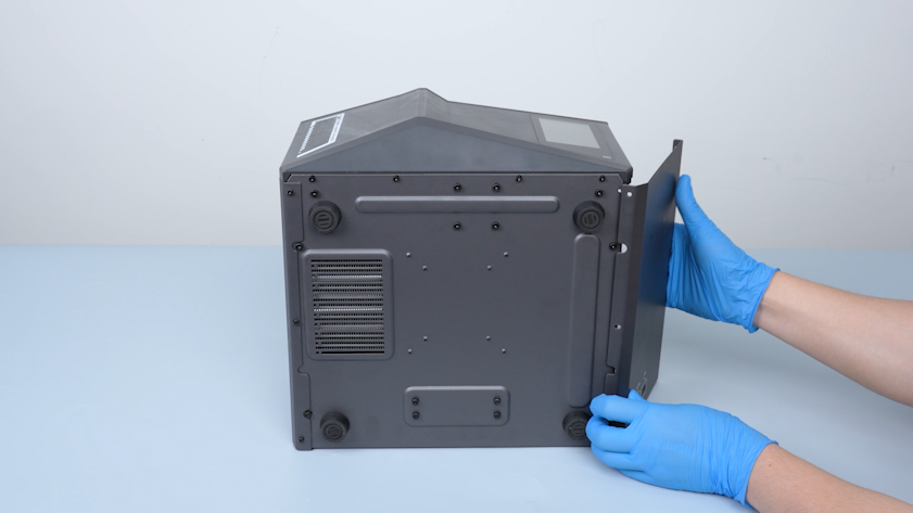
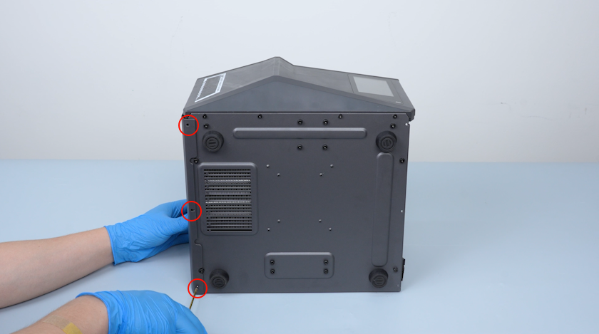
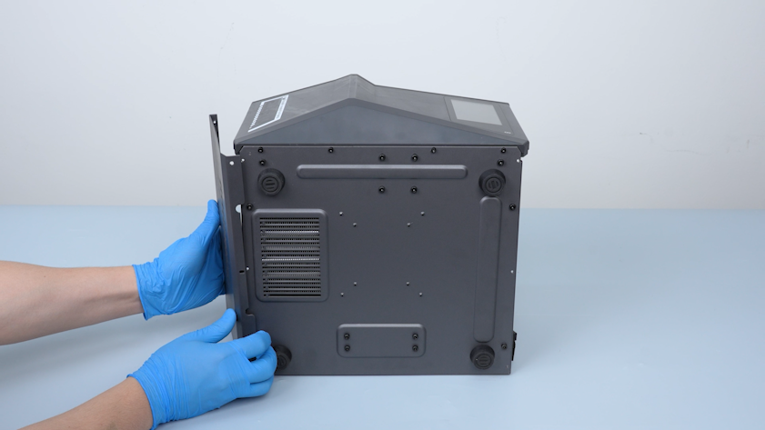
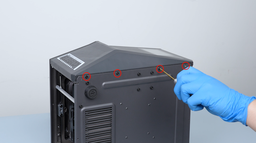
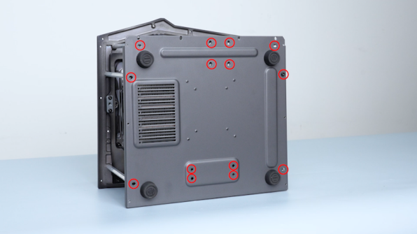
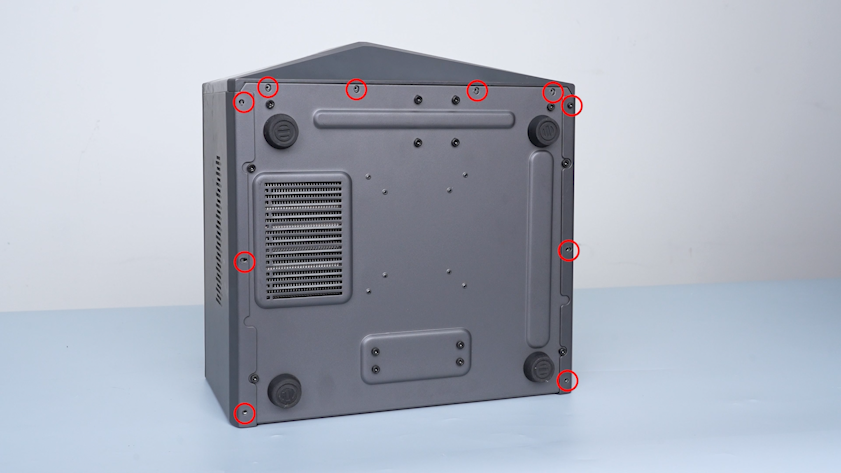
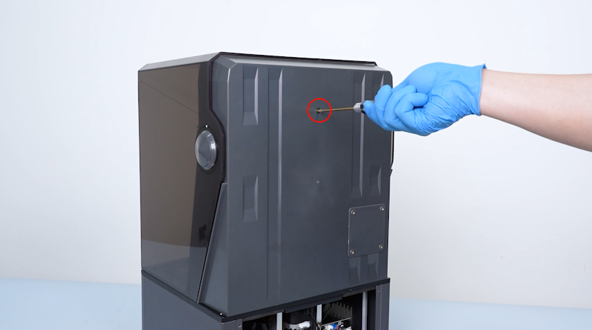
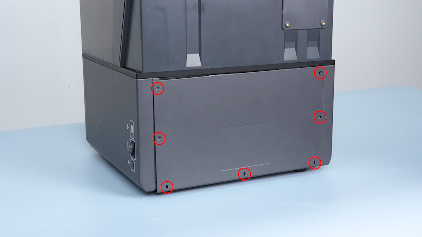
Release and remove the seven screws securing the back cover with a 2.0 mm Allen key. Remove the back cover.
-
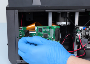
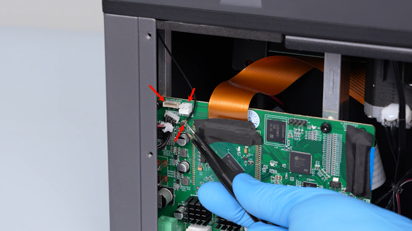
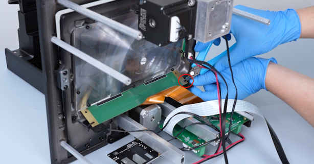
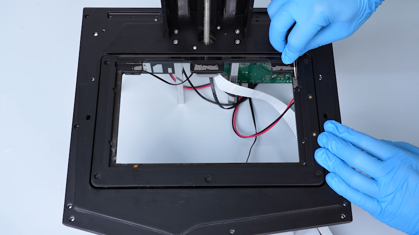
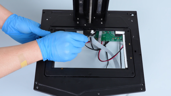
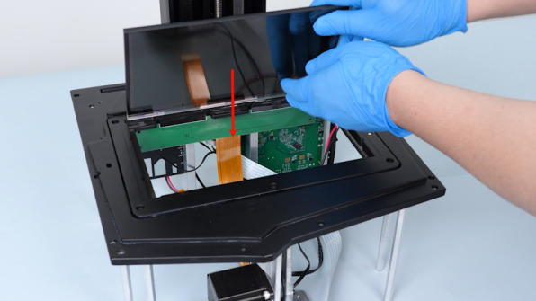
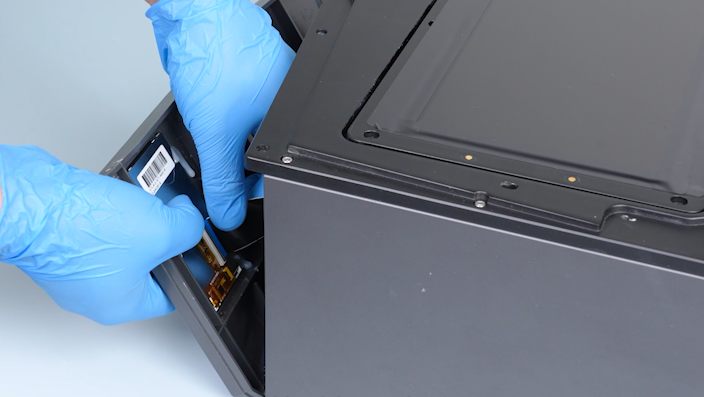
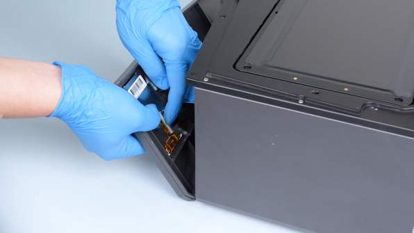
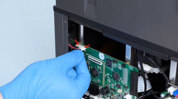
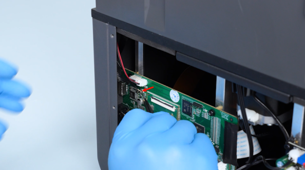
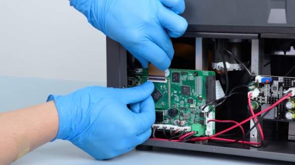
Remove the tape securing the LCD screen ribbon cable. Lift the clip. Remove the LCD screen ribbon cable.
-
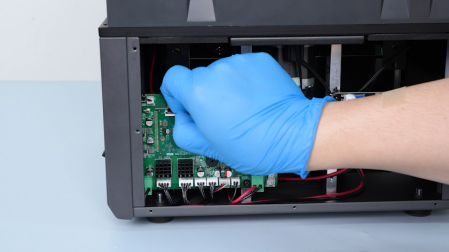
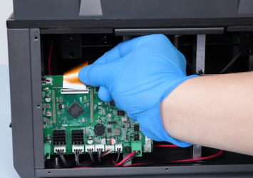
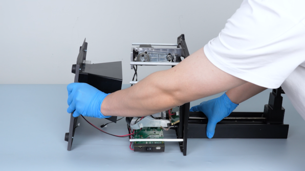
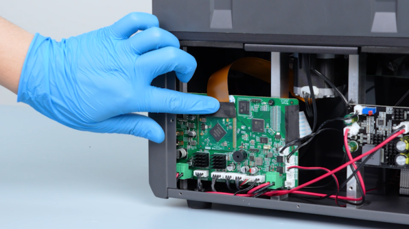
Remove the LED plug and the camera plug. Unplug the Wi-Fi antenna with a pair of tweezers.
-
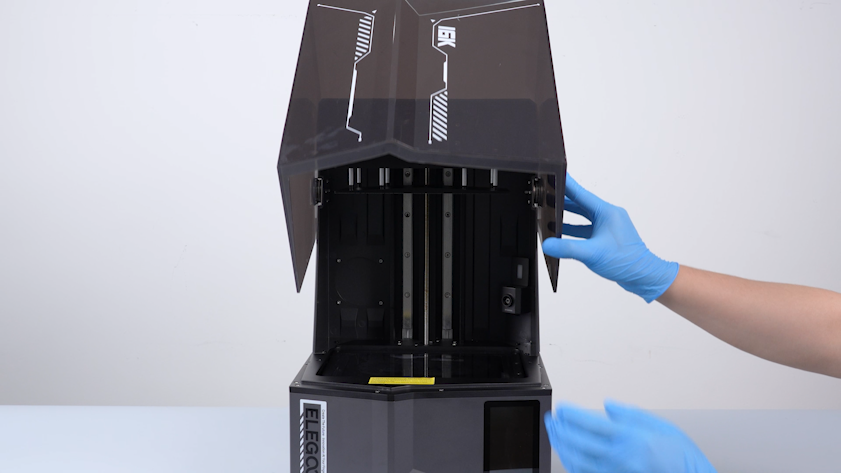
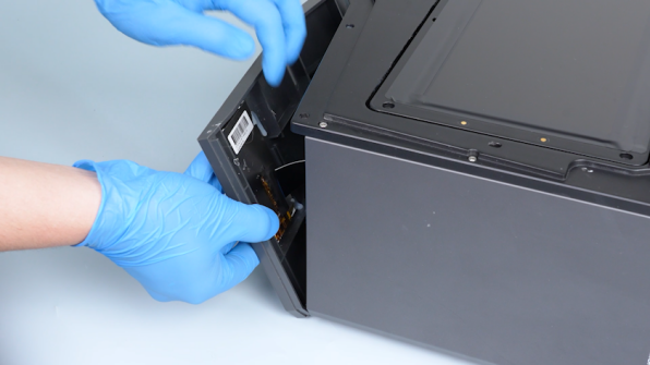
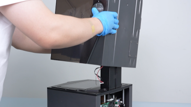
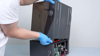
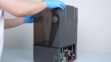
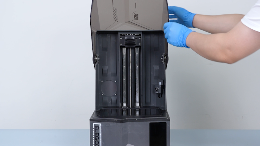
Lift the UV enclosure.
-
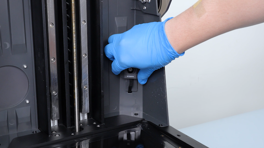
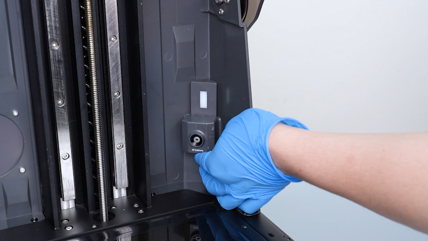
Raise the camera slightly.
-
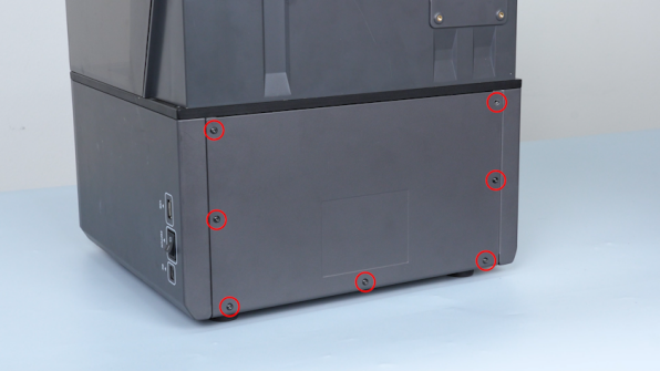
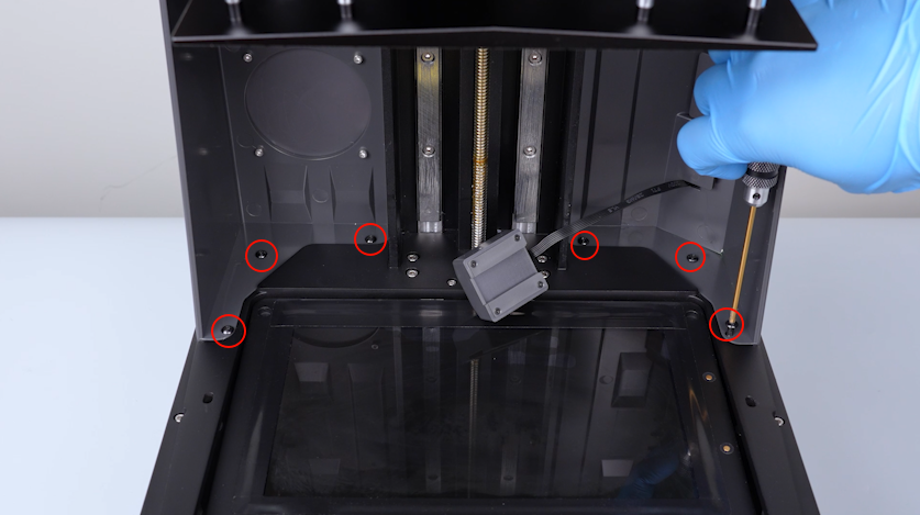
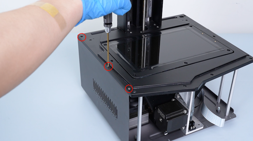
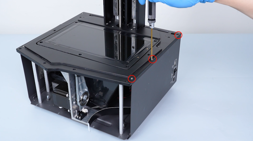
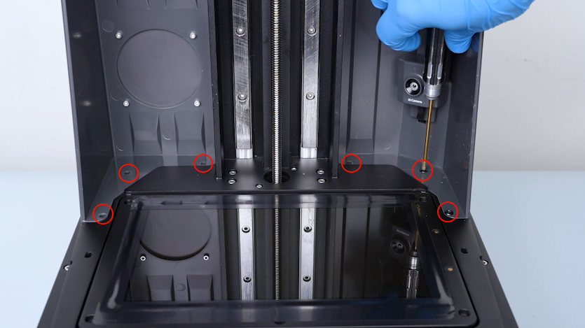
Release and remove the six screws securing the bottom of the housing assembly with a 2.5 mm Allen key.
-
Restore the UV enclosure.
-
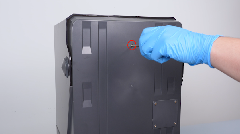
Release and remove the screw securing the back cover of the housing assembly with a 2.5 mm Allen key.
-
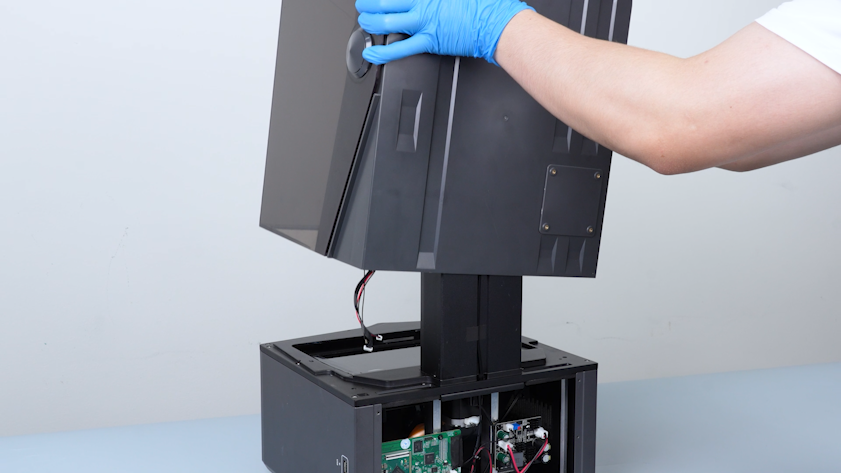
Remove the UV enclosure.
-
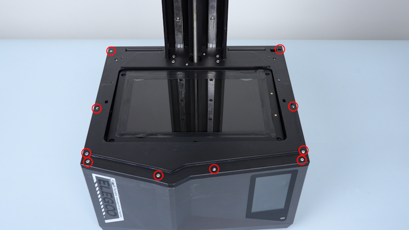
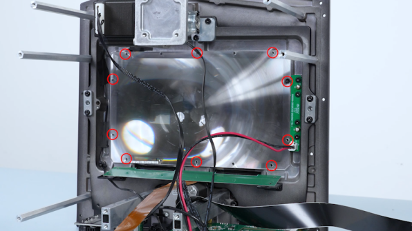
Release and remove the ten screws securing the edge of the middle panel with a 2.5 mm Allen key.
-
Release and remove the three screws securing the bottom of the right cover with a 2.5 mm Allen key.
-
Remove the right cover.
-
Release and remove the three screws securing the bottom of the left cover with a 2.5 mm Allen key.
-
Remove the left cover.
-
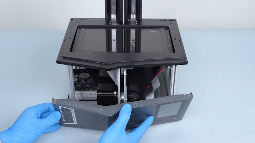
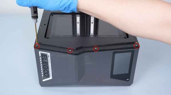
Release and remove the four screws securing the bottom of the front cover with a 2.5 mm Allen key.
-
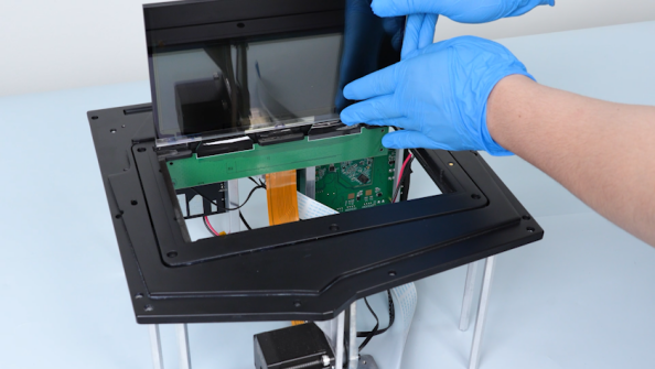
Carefully open the front cover.
-
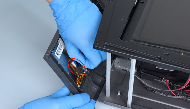
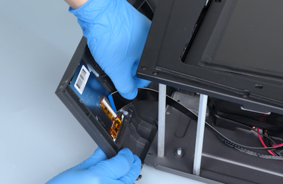
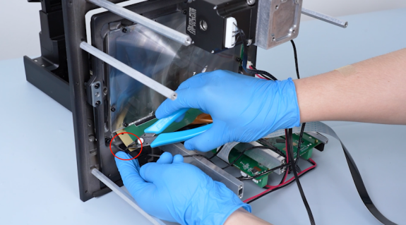
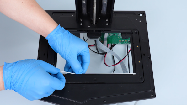
Remove the tape securing the touch screen ribbon cable. Lift the clip. Unplug the touch screen ribbon cable.
-
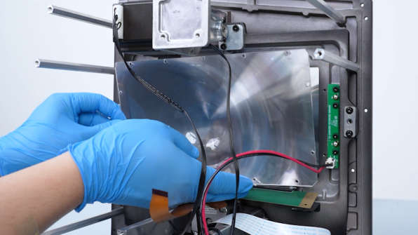
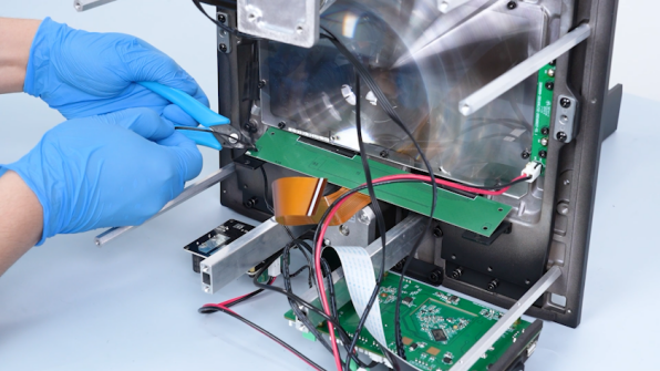
Cut off the cable ties securing the wires with a pair of pliers.
-
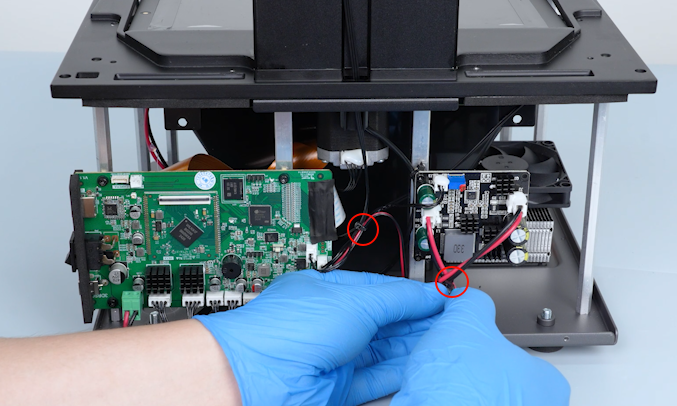
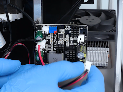
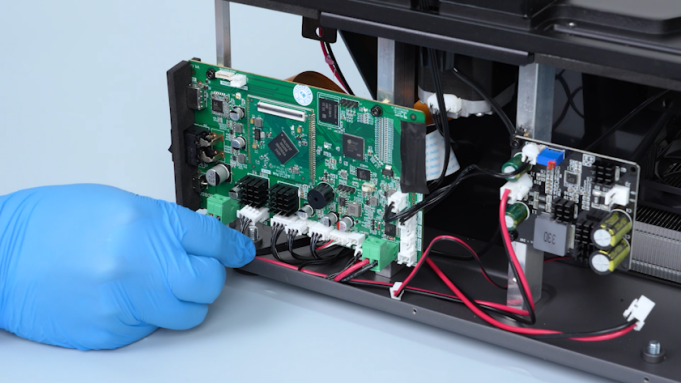
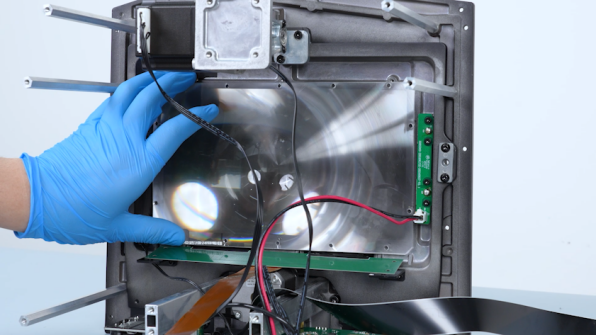
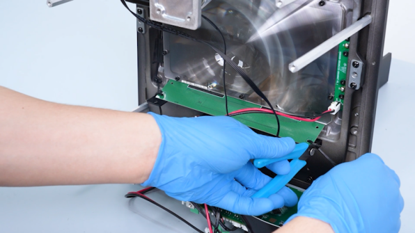
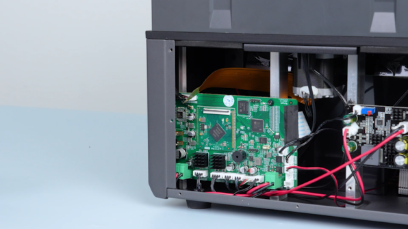
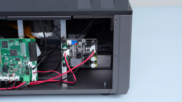
Remove the plugs on the UV light board and the motherboard.
-
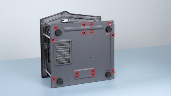
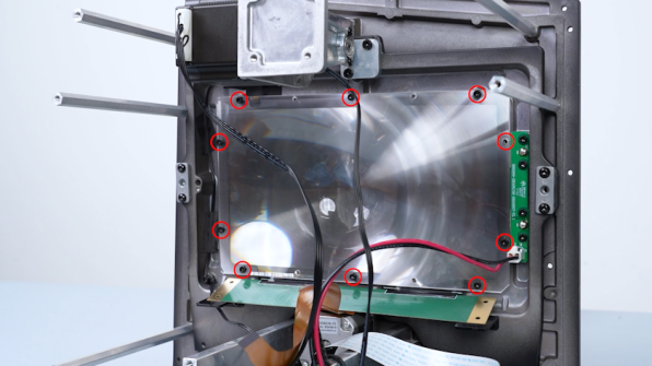
Release and remove the fourteen screws securing the edge of the bottom cover. Remove the bottom cover.
-
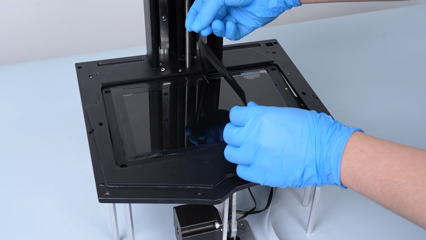
Peel off the tape securing the edge of the LCD screen.
-
Cut off the cable ties securing the PCB of the LCD screen.
-
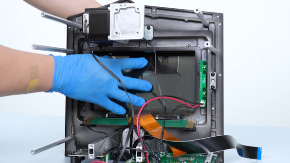
Release and remove the ten screws securing Fresnel lens. Remove Fresnel lens.
Note: Do not touch the Fresnel lens surface with bare hands.
-
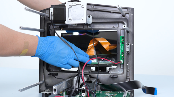
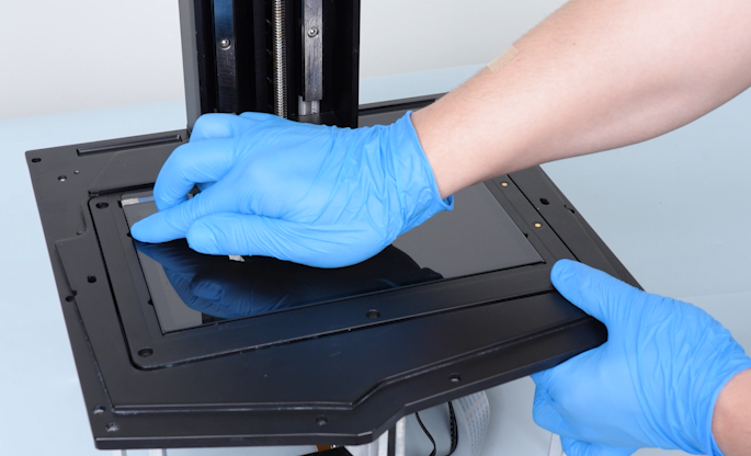
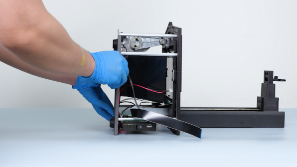
Push the LCD screen forward to separate it from the middle panel. Remove the LCD screen.
-
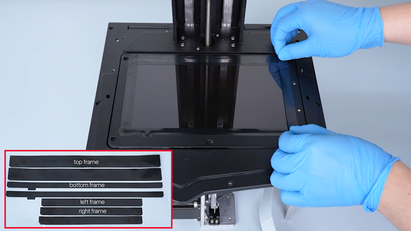
Clean the double-sided tape on the upper frame.
¶ Install the new LCD screen
-
Get the new LCD screen, ribbon cable, tape and cable ties.
-
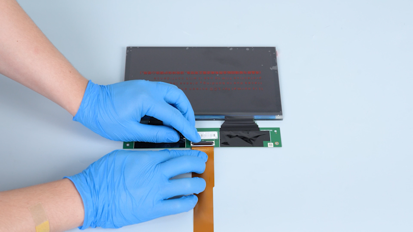
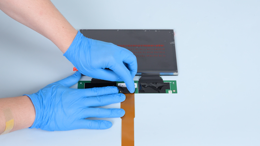
Lift the clip and insert the LCD screen ribbon cable into the port on the PCB.
-
Press the clip. Secure the LCD screen ribbon cable with tape.
-
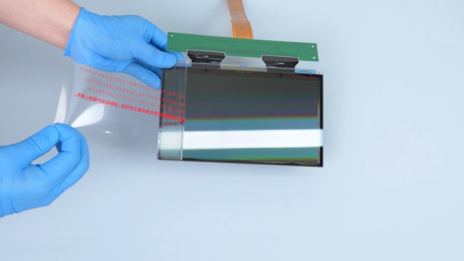
Adhere the double-sided tape to the lower frame of the LCD screen. Peel off the protective paper of the double-sided tape.
-
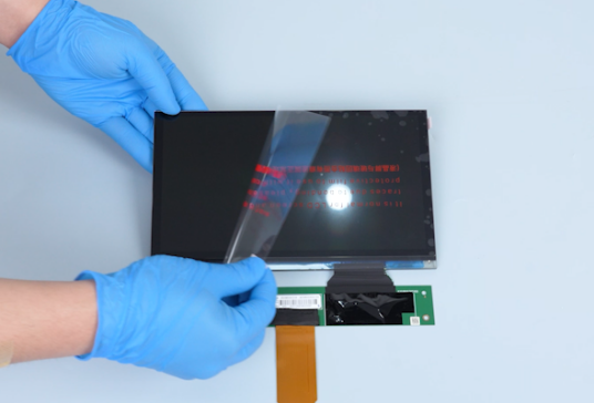
Peel off the protective films on both sides of the release film.
-
Put the LCD screen in the installation position.
Note: The LCD screen with the glass side must face downwards.
-
Hold the X-axis. Press the edge of the LCD screen.
-
Secure the edge with tape.
-
Put the Fresnel lens in the installation position. Tighten the ten screws securing Fresnel lens.
-
Secure the PCB of the LCD screen with cable ties.
-
Put the base in the installation position. Tighten the fourteen screws securing the base.
-
Put the left cover in the installation position. Tighten the three screws on the upper side of the left cover.
-
Put the right cover in the installation position. Tighten the three screws on the upper side of the right cover.
-
Get the front cover and insert the ribbon cable of the touch screen into the port on the back cover of the touch screen.
-
Press the clip. Secure the touch screen ribbon cable with tape.
-
Put the front cover in the installation position. Tighten the four screws on the upper side of the front cover.
-
Tighten the ten screws securing the bottom of the front cover, left cover and right cover.
-
Put the housing on the middle panel temporarily. Insert the Wi-Fi antenna, camera wire and LED wire through the slot in the middle panel. Install the housing assembly.
-
Tighten the screw securing the back of the housing assembly.
-
Lift the UV enclosure.
-
Tighten the six screws securing the bottom of the housing assembly.
-
Restore the camera.
-
Insert the plugs on the UV light board and the motherboard.
-
Put the back cover in the installation position. Tighten the five screws securing the back cover.
¶ Verification
-
Plug in the power adapter cable. Turn the power switch ON (symbol "|").
-
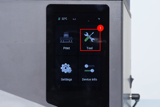
On the touch screen, select Tool - Exposure - ELEGOO.
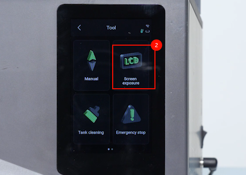
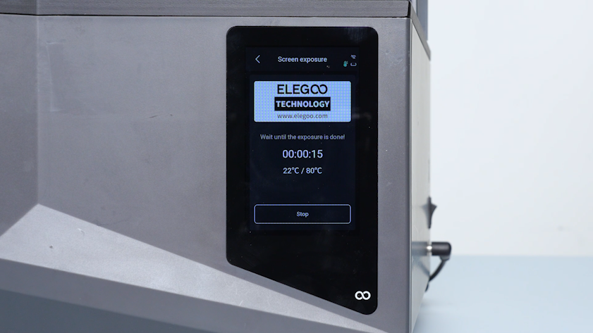
-
Confirm that the ELEGOO logo displays normally. The LCD screen is replaced successfully.
