¶ Tools and Materials
-
2.0 mm Allen key x 1
-
2.5 mm Allen key x 1
-
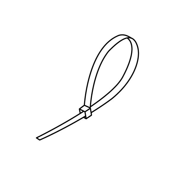
Cable ties
-
A new power supply

¶ Instruction
¶ Preparation
Turn the power switch OFF (symbol "〇") and unplug the power supply cable.
¶ Remove the old power supply
-
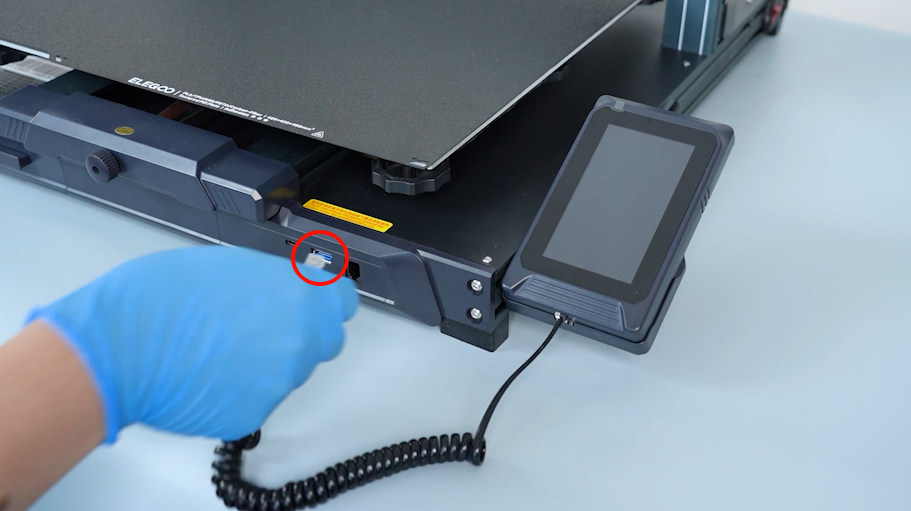
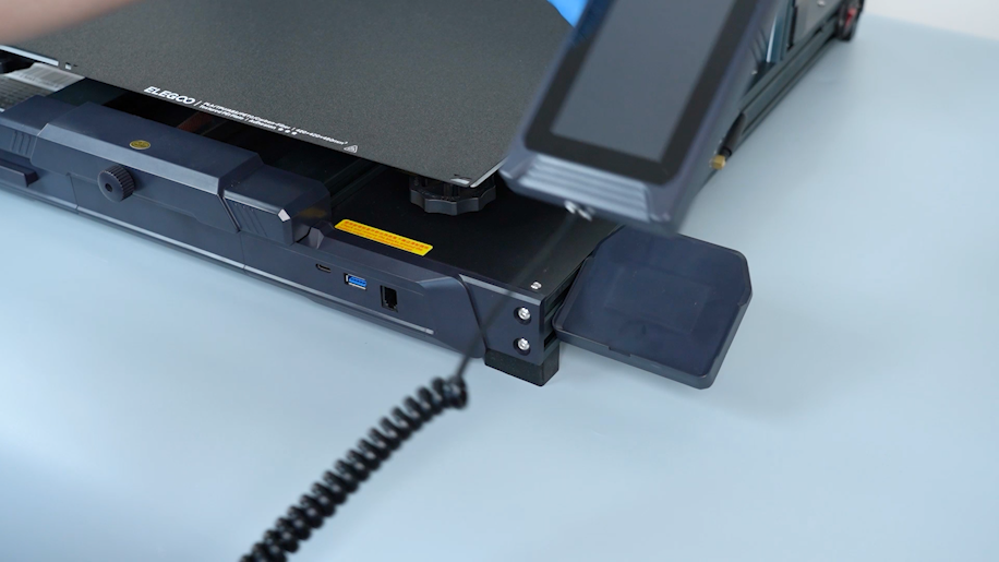
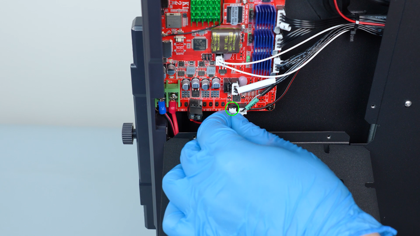
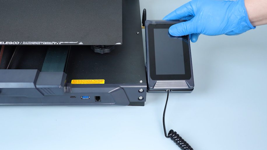
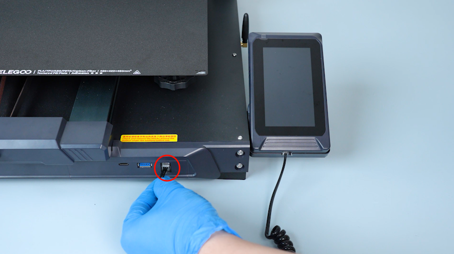
Disconnect the touch screen wire and remove the touch screen.
-
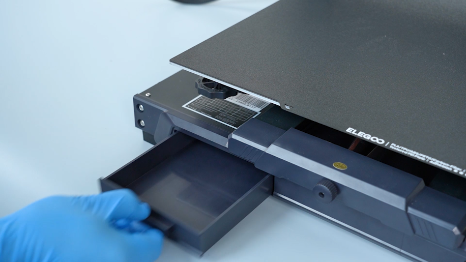
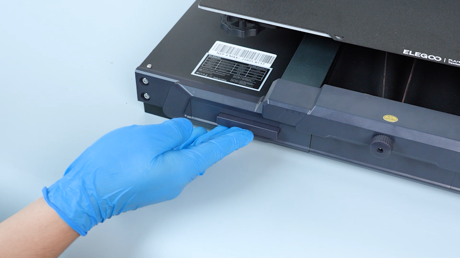
Remove the tool drawer.
-
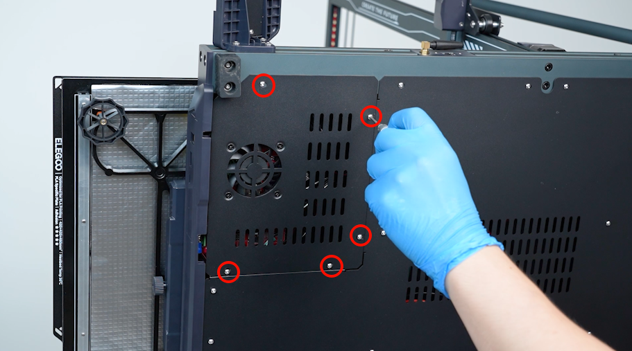
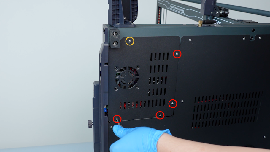
Remove the five screws securing the motherboard cover with a 2.0 mm Allen key.
-
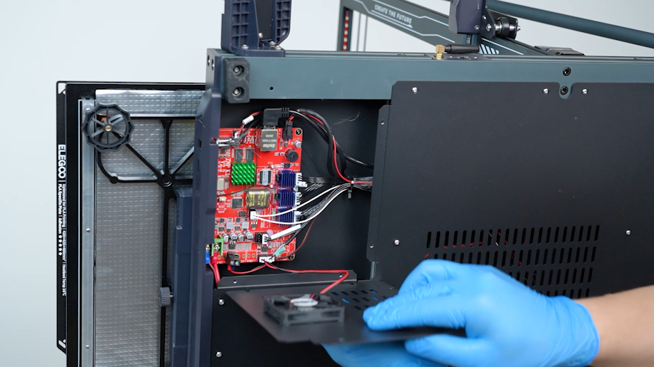
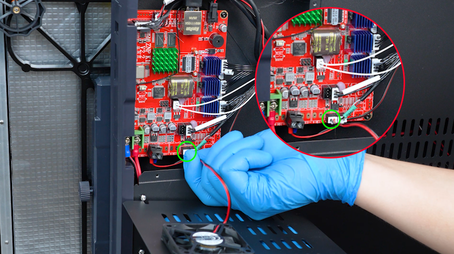
Remove the bottom cover carefully. Disconnect the cable of the motherboard cooling fan.
-
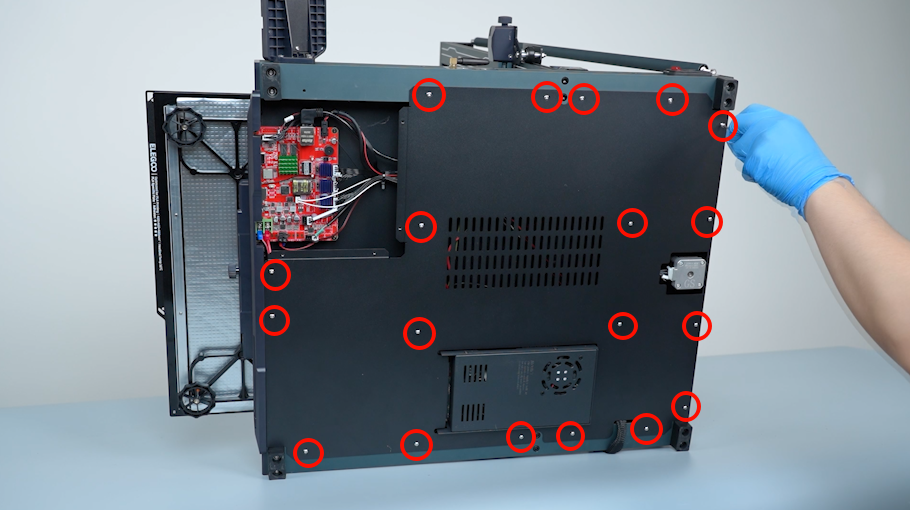
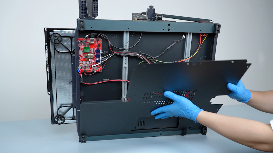
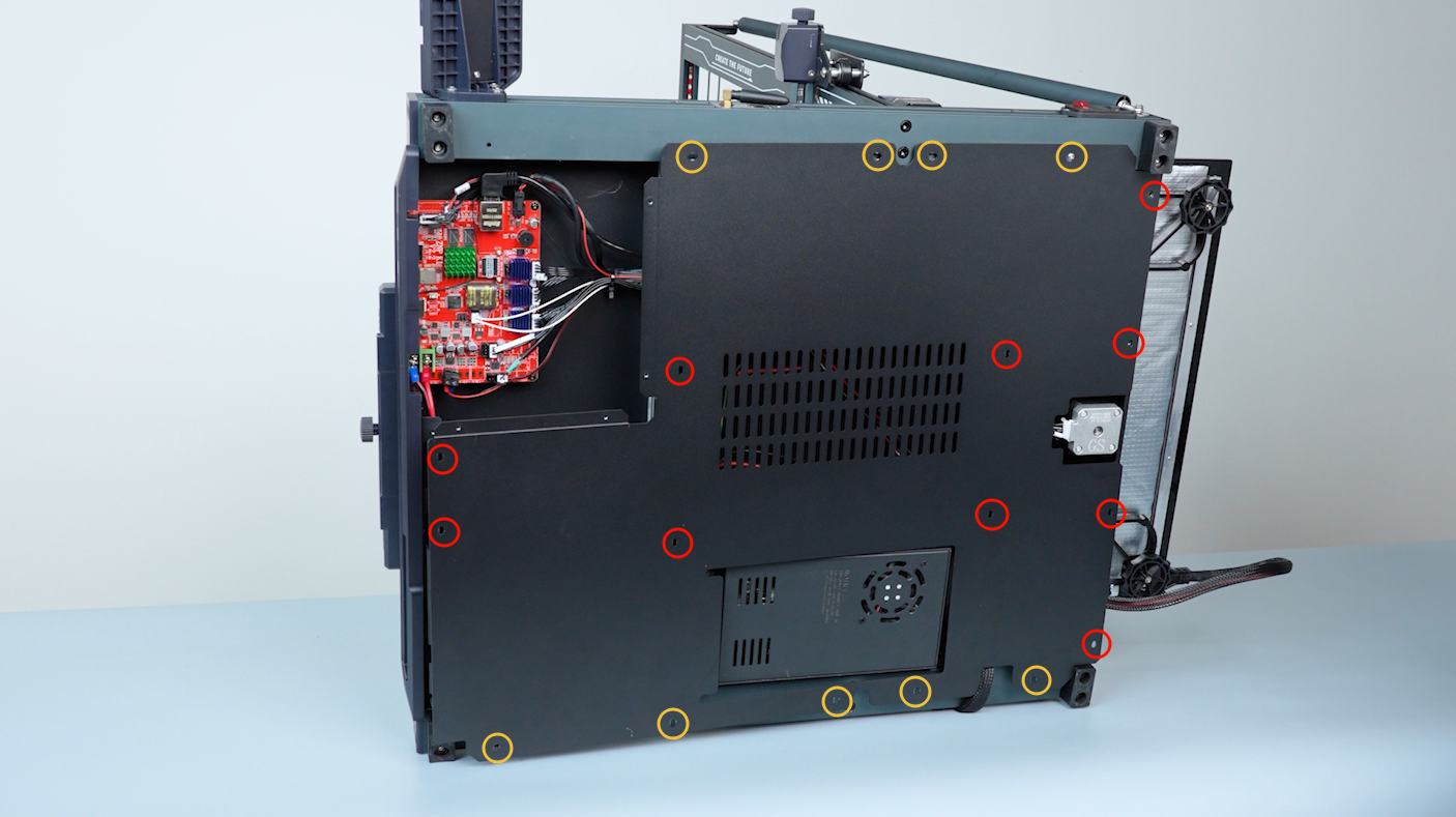
Loosen the nineteen screws securing the bottom cover with a 2.0 mm Allen key. Hold the bottom cover and remove it.
-
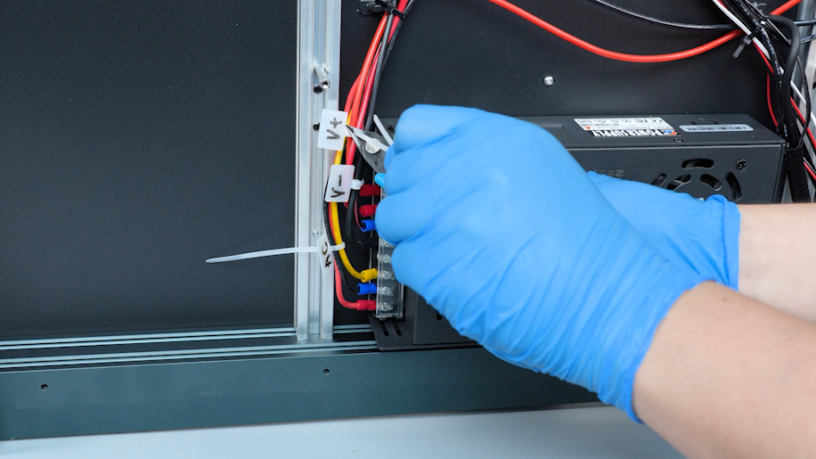
Secure the power cables with cable ties. Label the power cables and trim the excess parts of the cable ties.
-
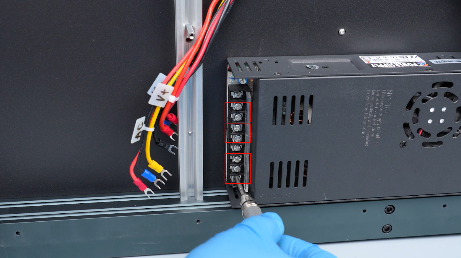
Remove the power supply cover. Loosen the screws securing the power cables with a Phillips screwdriver and disconnect them.
-
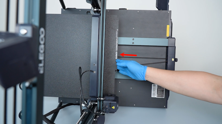
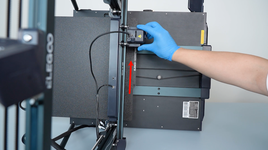
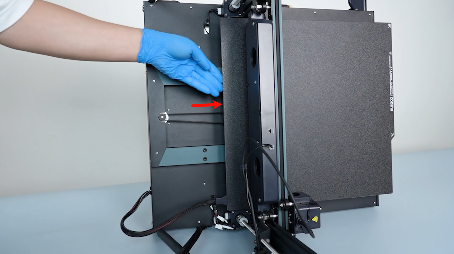
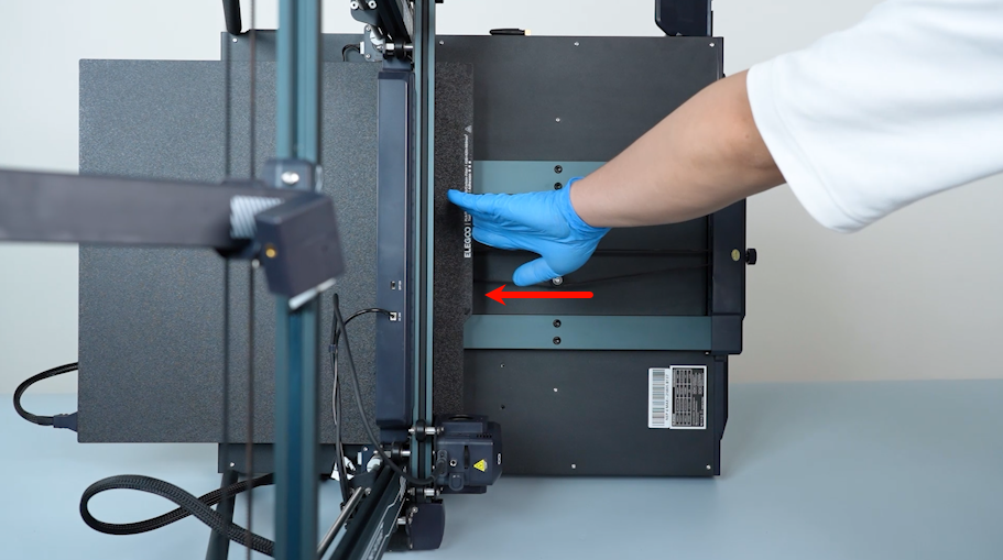
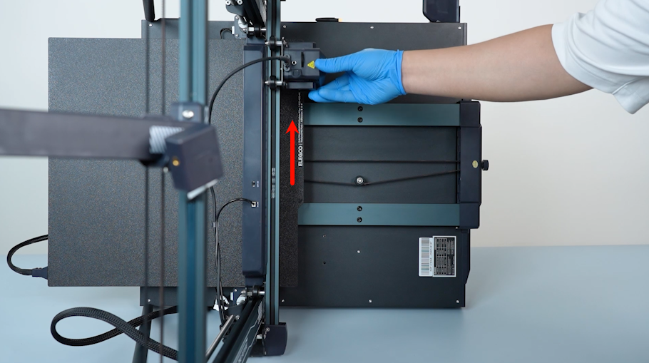
Push the heated bed to the left and push the extruder upward.
-
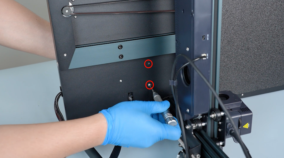
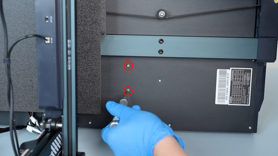
Release and remove the two screws securing the power supply with a 2.5 mm Allen key.
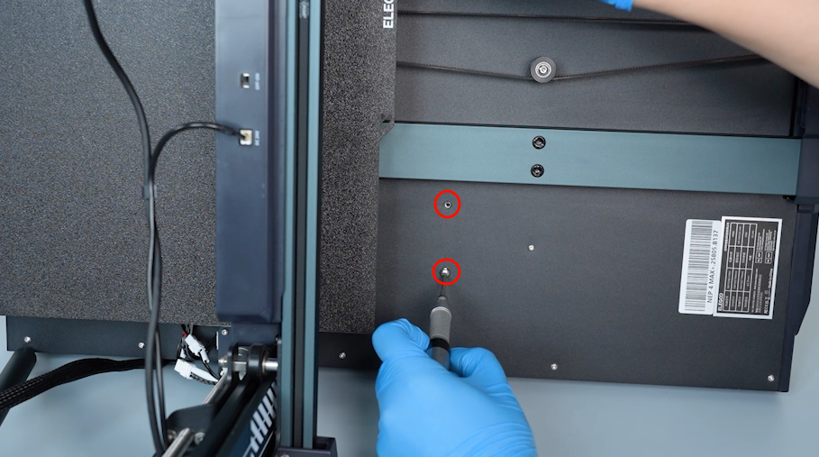
-
Push the heated bed to the right. Release and remove the two screws securing the power supply with a 2.5 mm Allen key.
-
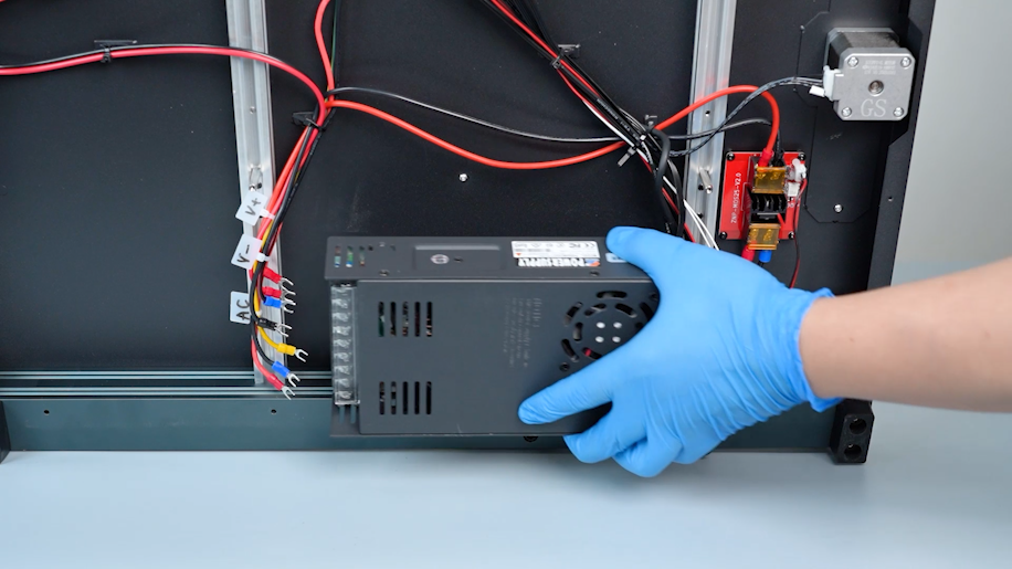
Hold the power supply when releasing the last screw. Remove the old power supply.
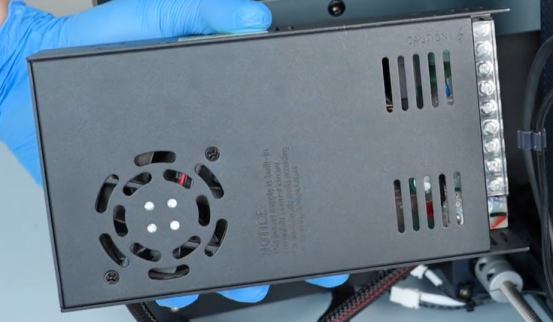
¶ Preparation before installation
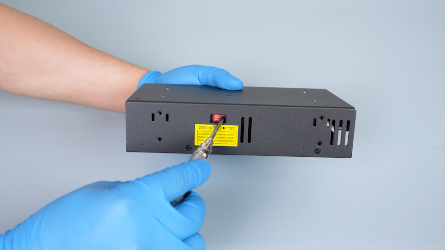
Before installing the new power supply, make sure that the power supply is set to correct voltage.
Incorrect power supply voltage may damage the power supply.
¶ Install the new power supply
-
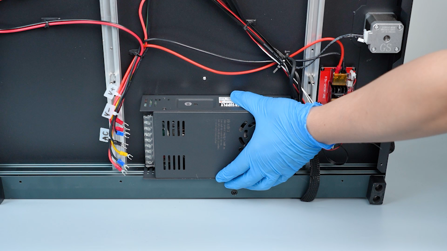
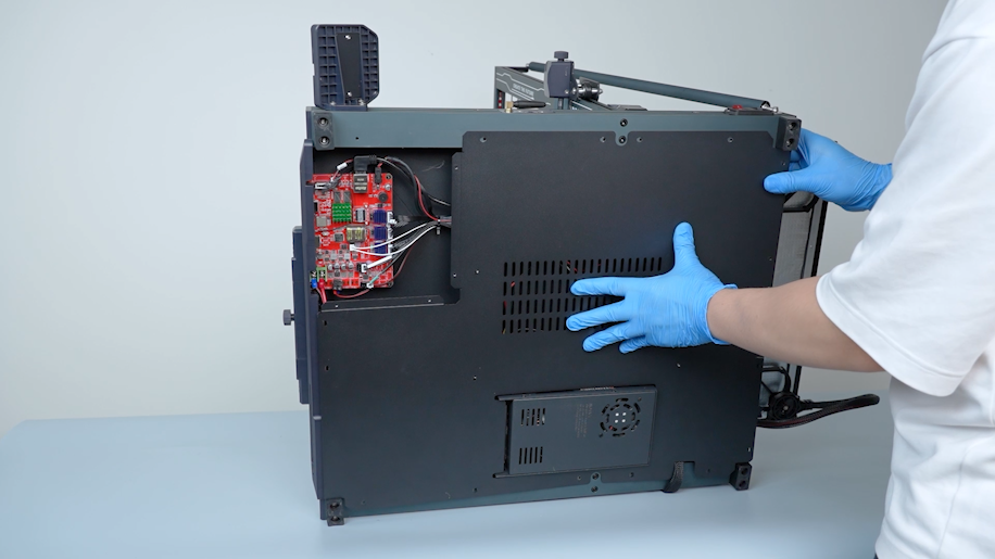
Prepare the new power supply and align the new power supply with the screw holes on the base.
-
Hold the power supply. Tighten the two screws securing the power supply with a 2.5 mm Allen key.
-
Push the heated bed to the left and push the extruder upward.
-
Tighten the two screws securing the power supply with a 2.5 mm Allen key.
-
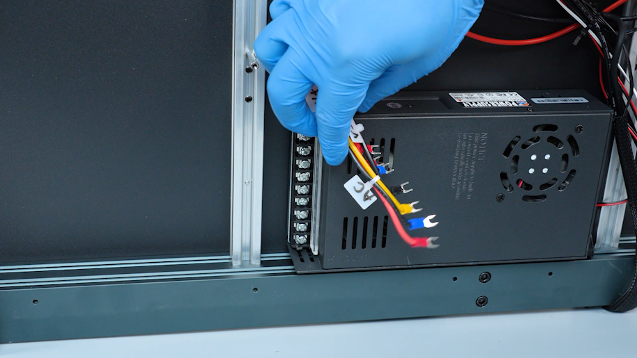
Lift the cover of the new power supply. Loosen the screws securing the power supply ports with a Phillips screwdriver.
-
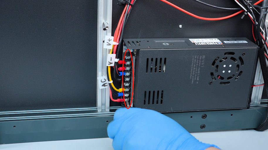
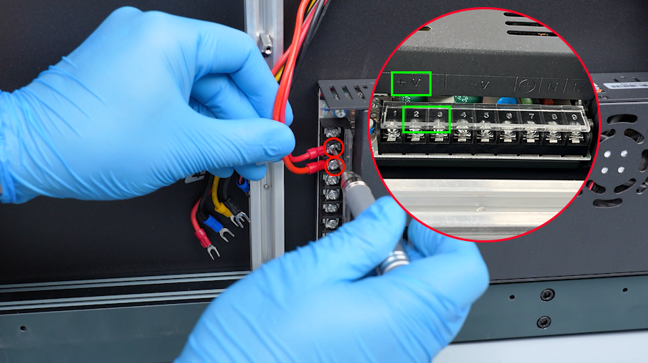
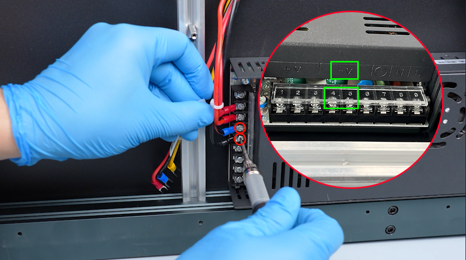
According to the labels, insert the two red wires marked V+ into the V+ port.
-
Insert the two black wires marked V- into the V- ports.
-
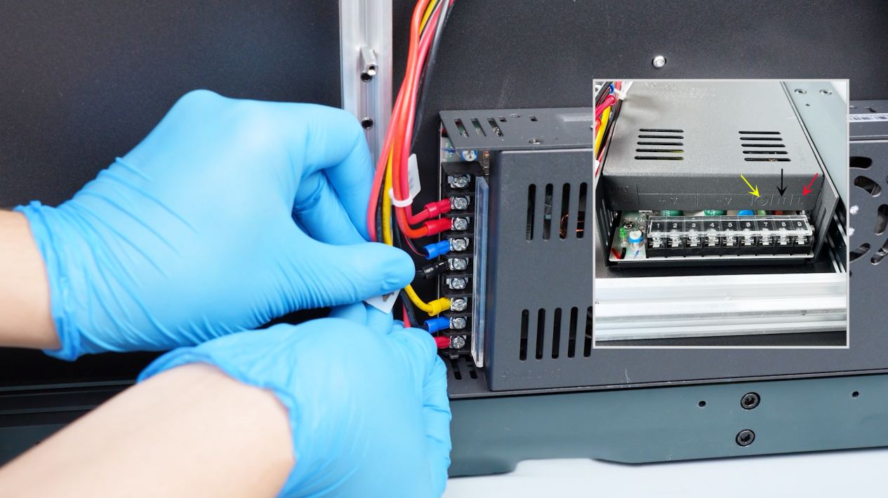
Insert the yellow wire to the grounding port.
-
Insert the black wire to the N port.
-
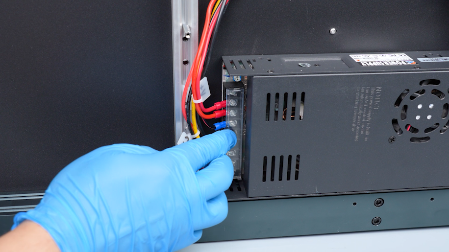
Insert the red wire to the L port.
-
Tighten the screws with a Phillips screwdriver and close the power supply cover.
-
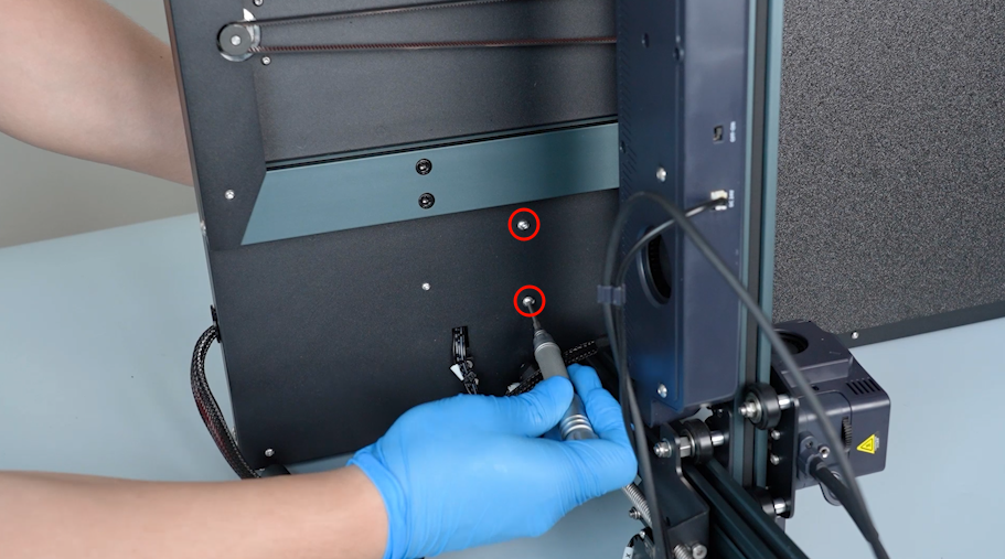
Install the bottom cover and hold it in place. Tighten the screws securing the bottom cover with a 2.0 mm Allen key.
Note: Screws labeled by the red circle are M3 x 6, and screws labeled by the yellow circle are M3 x 16.
-
Prepare the motherboard cover. Plug in the cable of the motherboard cooling fan.
-
Close the motherboard cover and hold it. Tighten the screws securing the motherboard cover with a 2.0 mm Allen key.
Note: Screws labeled by the red circle are M3 x 6, and screws labeled by the yellow circle are M3 x 16.
-
Install the tool drawer.
-
Put the touch screen on the bracket and plug in the wire.
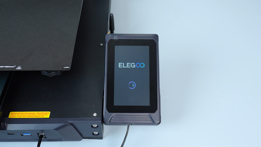
¶ Verification
-
Plug in the power supply cable. Turn the power switch ON (symbol "|") .
-
Confirm that the touch screen works normally. The printer is ready for use.