¶ Tools and Materials
-
2.5 mm Allen key x 1
-
2.0 mm Allen key x 1
-
1.5mm Allen key x 1
-
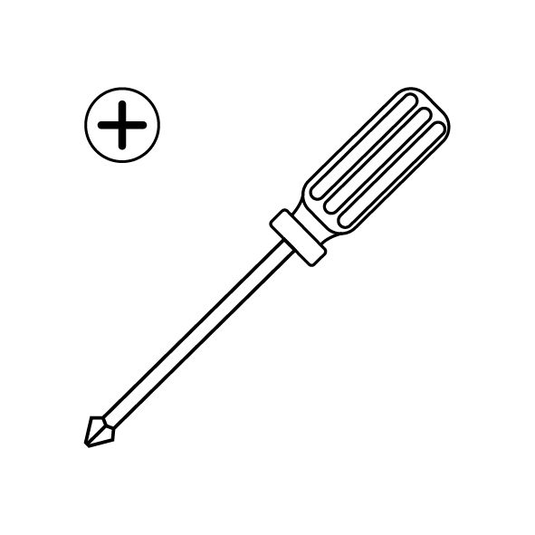
A Phillips screwdriver
-
A new heat break cooling fan
¶ Instruction
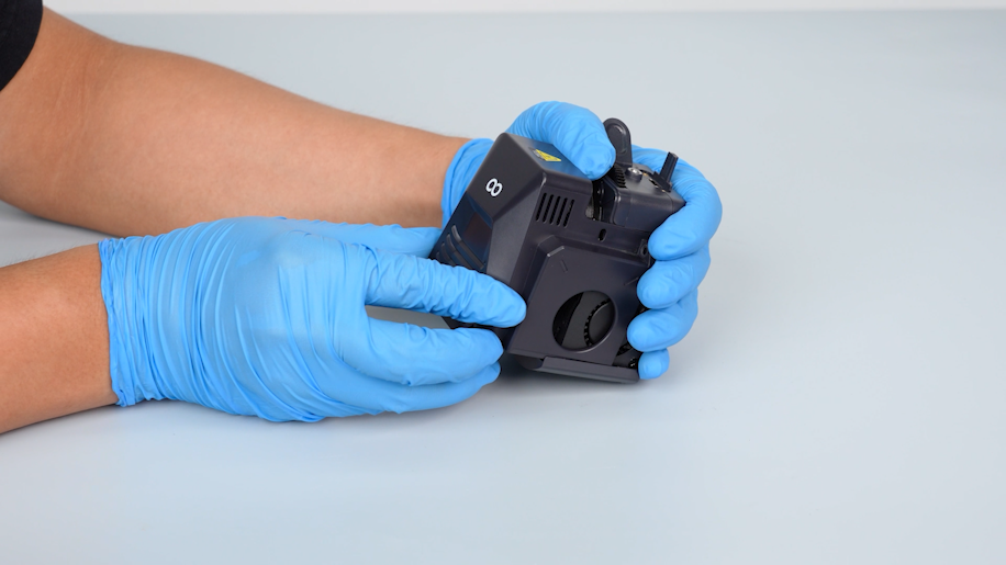
¶ Preparation
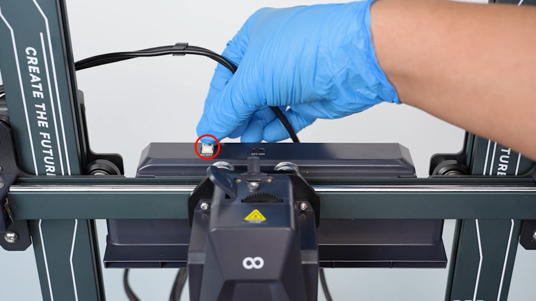
Turn the power switch OFF (symbol "〇") and unplug the power supply cable.
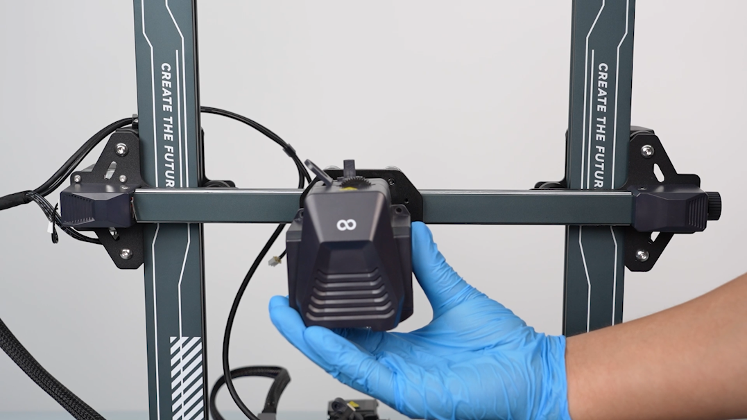
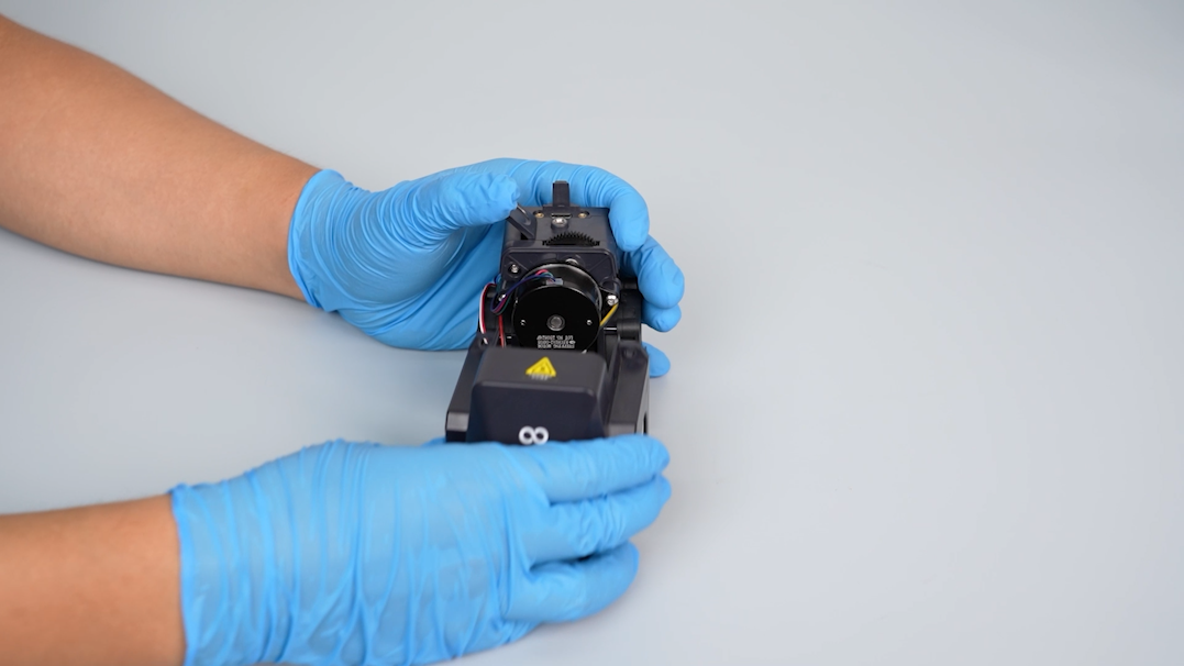
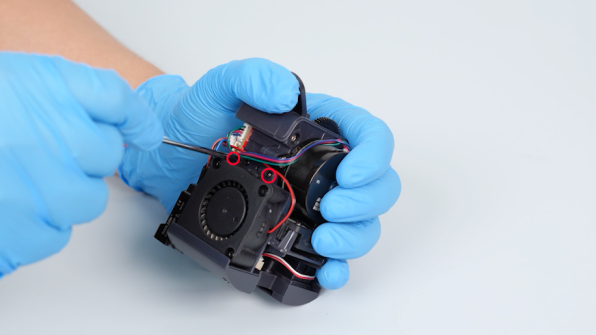
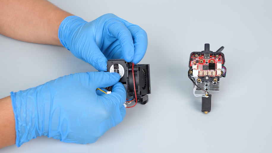
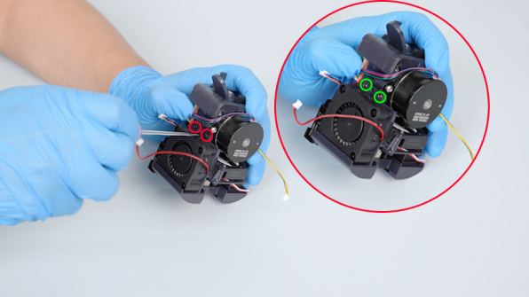
¶ Remove the rear cooling fan assembly
-
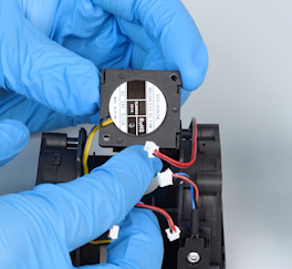
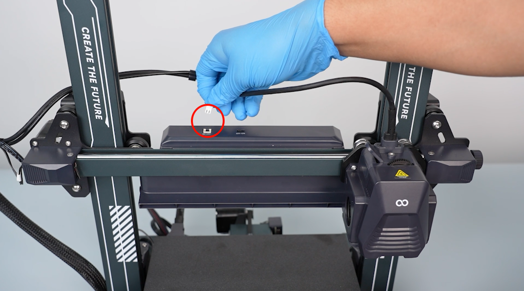
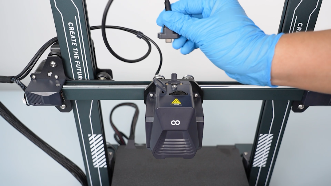
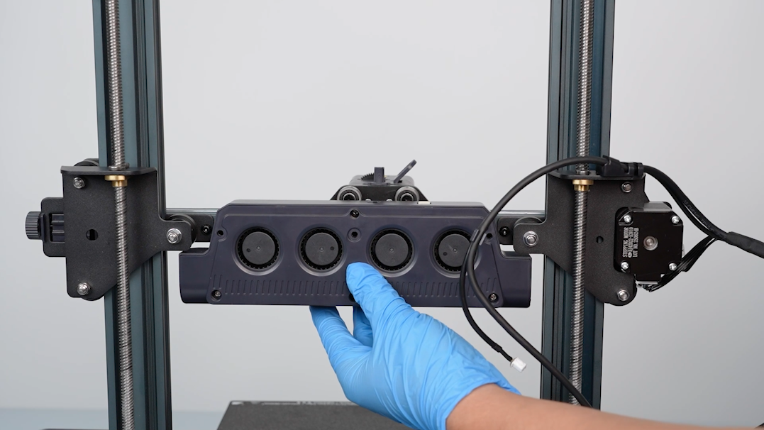
Unplug the cables of the rear cooling fan assembly.
-
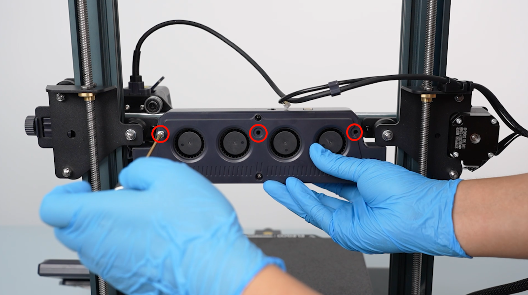
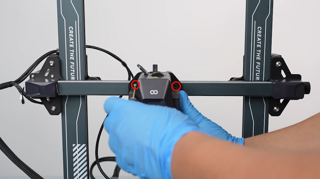
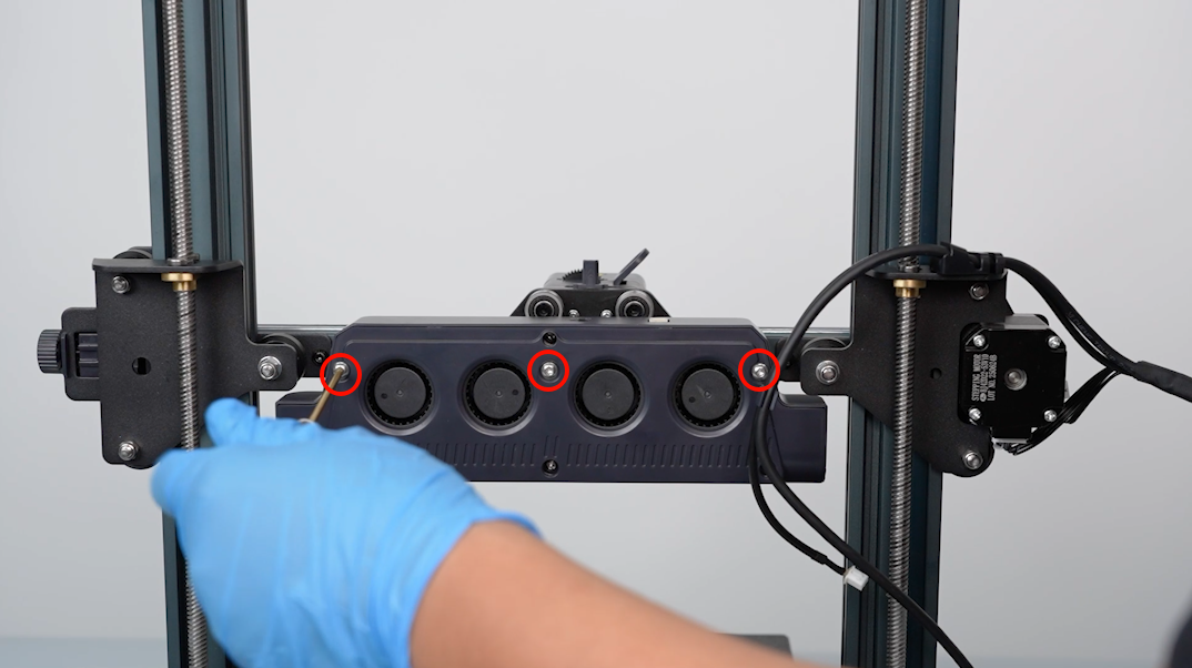
Loosen the three screws securing the rear cooling fan assembly with a 2.5 mm Allen key.
-
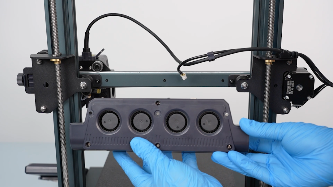
Remove the rear cooling fan assembly.
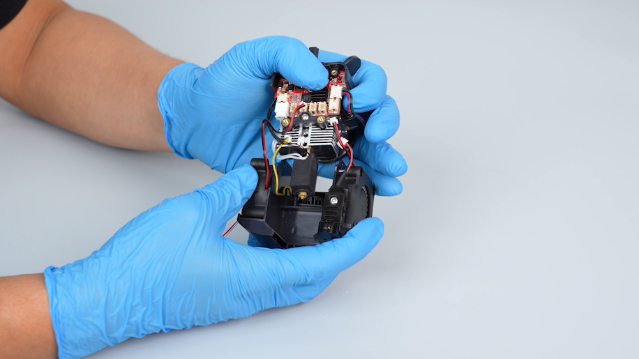
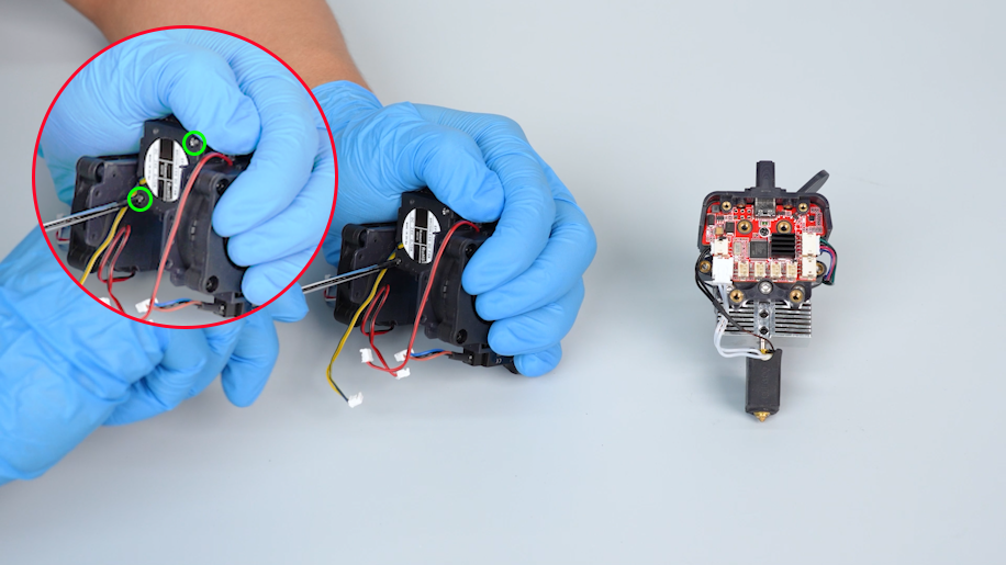
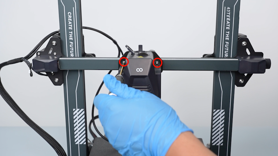
¶ Remove the print head assembly
-
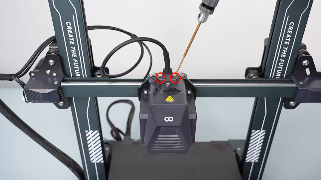
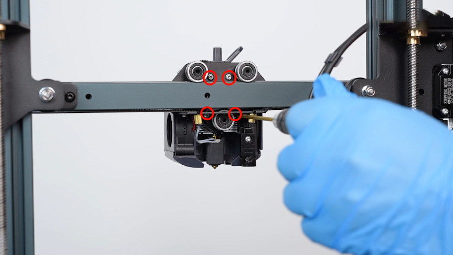
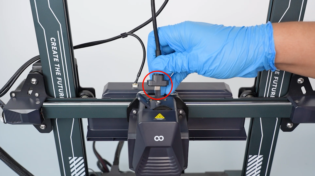
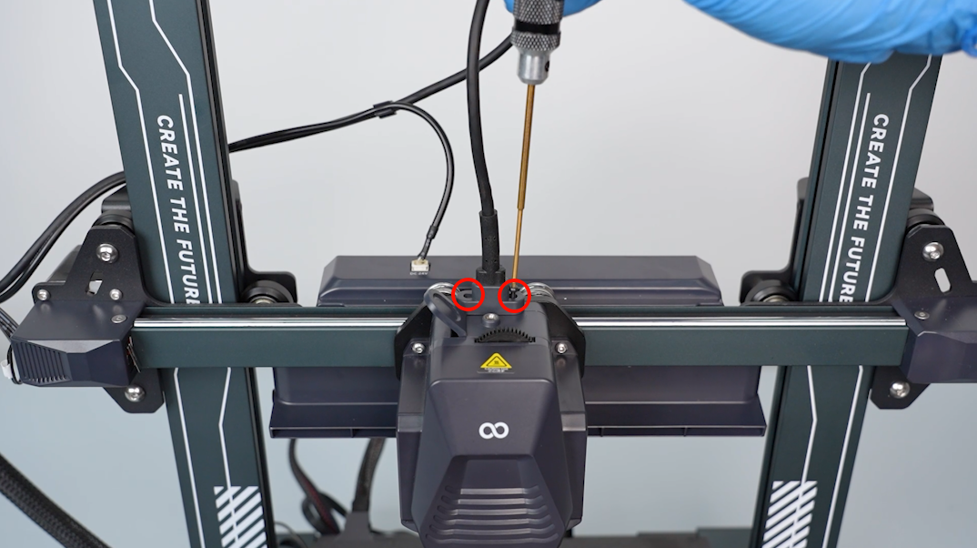
Loosen the two screws securing the print head connection cable with a 1.5 mm Allen key.
-
Disconnect the connection cable of the print head.
-
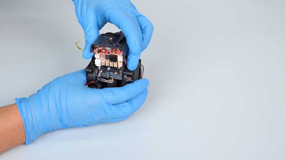
Loosen the four screws securing the back of the print head assembly with a 2.0 mm Allen key.
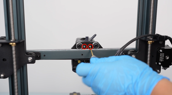
-
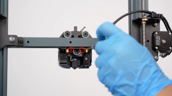
Loosen the two screws securing the front cover of the print head with a 2.0 mm Allen key.
-
Remove the print head assembly.
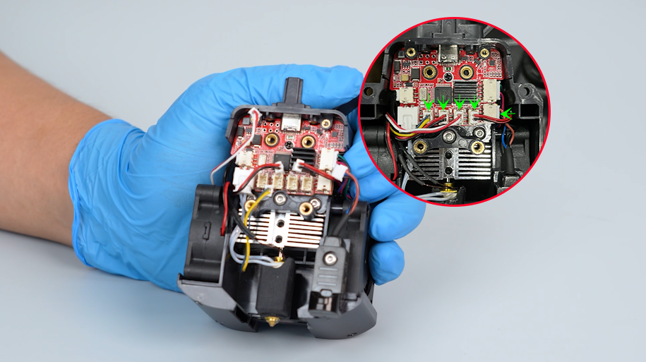
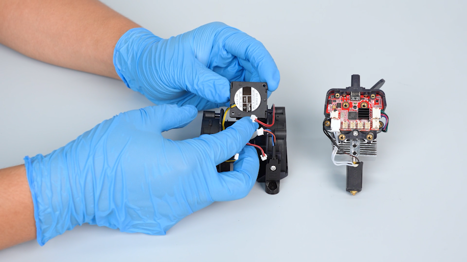
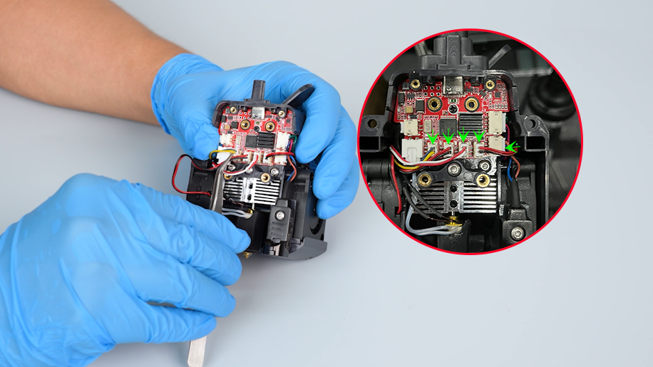
¶ Remove the model cooling fan support
-
Remove the front cover of the print head.
-
Disconnect the cables of the heat break cooling fan, model cooling fan, nozzle light and leveling sensor from the print head adapter board.
-
Loosen the four screws on the two sides of the model cooling fan support with a Phillips screwdriver.
-
Pull model cooling fan support downward and remove it.
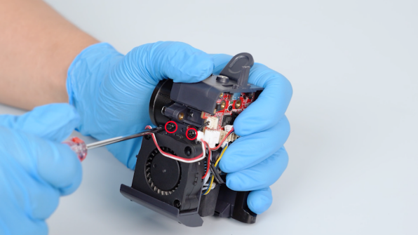
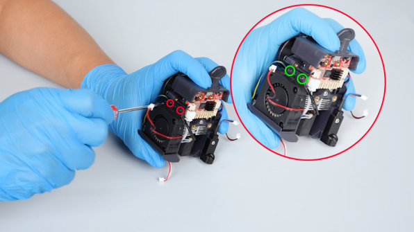
¶ Remove the old heat break cooling fan
-
Loosen the two screws securing the heat break cooling fan with a Phillips screwdriver.
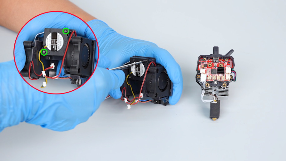
-
Remove the old heat break cooling fan.
¶ Install the new heat break cooling fan
-
Prepare the new heat break cooling fan and put it in the installation position.
-
Tighten the two screws securing the heat break cooling fan with a Phillips screwdriver.
¶ Install the model cooling fan support
-
Organize the cables and put the model cooling fan support in the installation position.
-
Tighten the four screws on the two sides of the model cooling fan support with a Phillips screwdriver.
¶ Install the print head assembly
-
Insert the cables of the heat break cooling fan, model cooling fan, nozzle light and leveling sensor on the print head adapter board.
-
Organize the internal cables of the print head. Install the front cover of the print head assembly.
-
Put the print head assembly in the installation position. Tighten the two screws securing the front cover of the print head with a 2.0 mm Allen key.
-
Tighten the four screws securing the back of the print head assembly with a 2.0 mm Allen key.
¶ Install the rear cooling fan assembly
-
Prepare the rear cooling fan assembly. Align it with the screw holes and put it in the installation position.
-
Tighten the three screws securing the rear cooling fan assembly with a 2.5 mm Allen key.
-
Plug in the cables of the rear cooling fan assembly.
-
Insert the connection cable of the print head into the port.
-
Tighten the two screws securing the connection cable port of the print head with a 1.5 mm Allen key.
¶ Verification
-
Plug in the power supply cable and turn the power switch ON (symbol "|").
-
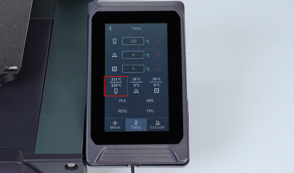
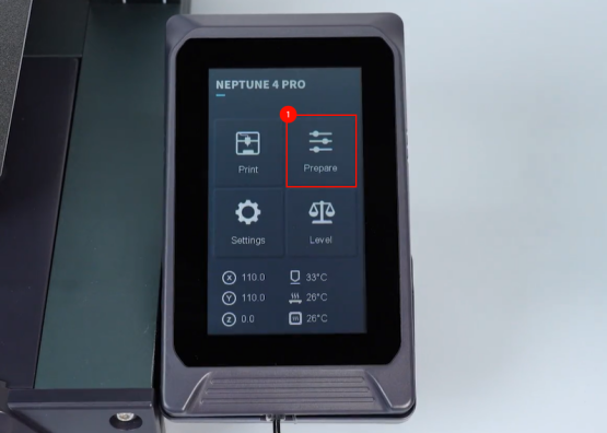
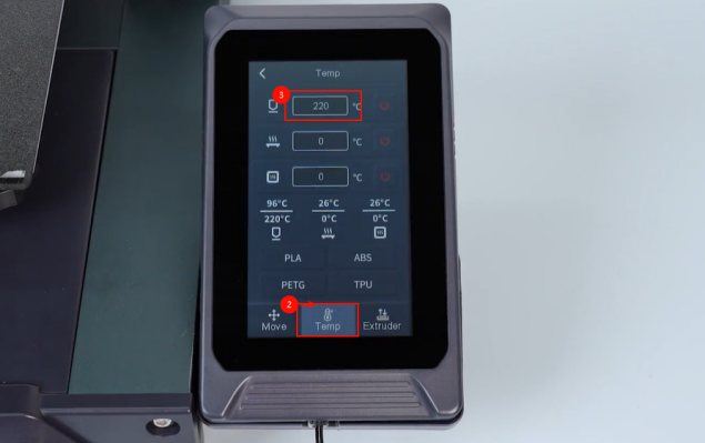
On the touch screen, select Prepare - Temperature. Set the temperature of the nozzle to 220 ℃.
-
The heat break cooling fan works normally. The printer is ready for use after it is re-leveled.