¶ Tools and Materials
-
2.0 mm Allen key x 1
-
2.5 mm Allen key x 1
-
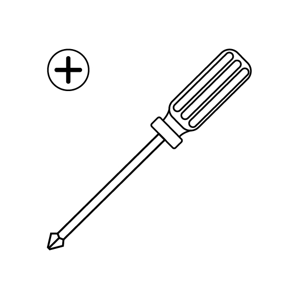
A Phillips screwdriver
-
A new gear of the extruder
¶ Instruction
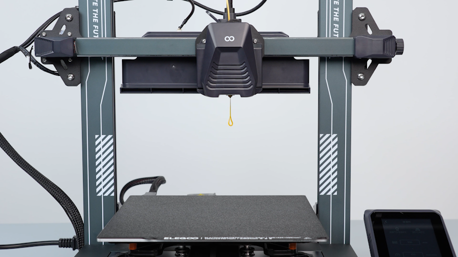
¶ Preparation
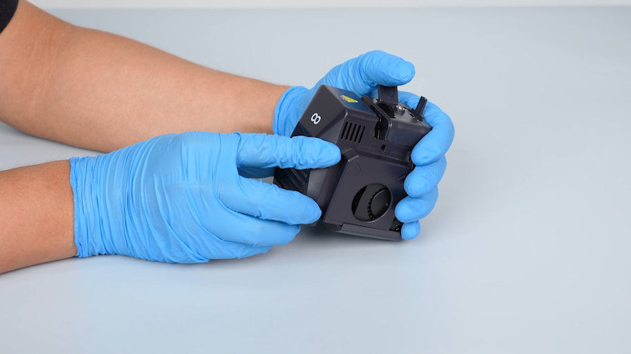
Turn the power switch OFF (symbol "〇") and unplug the power supply cable.
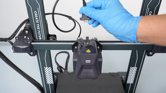
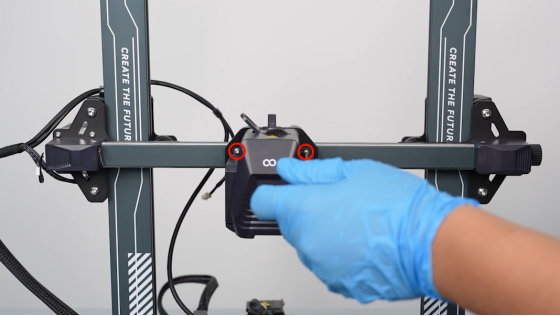
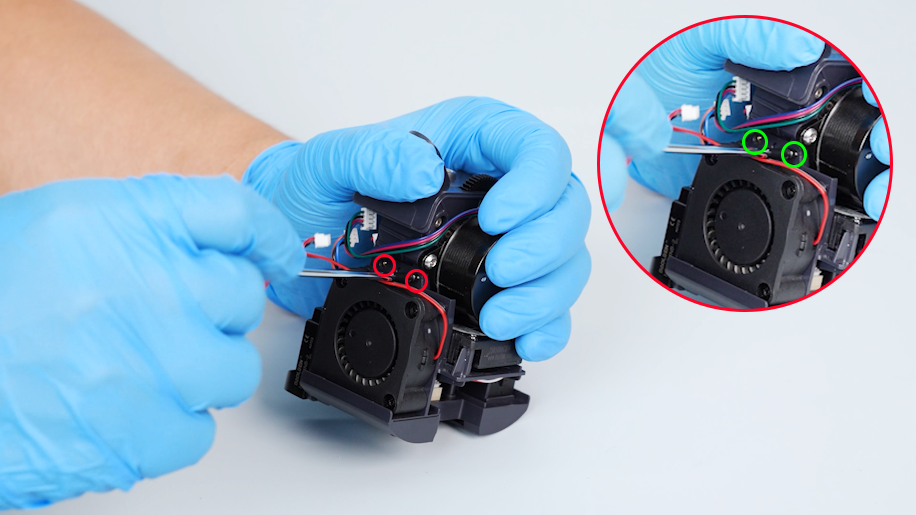
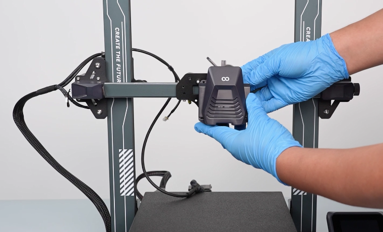
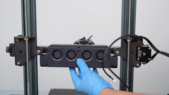
¶ Remove the rear cooling fan assembly
-
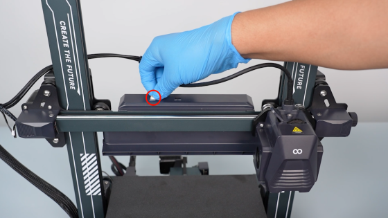
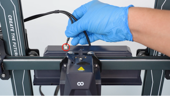
Unplug the cables of the rear cooling fan assembly.
-
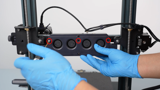
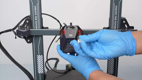
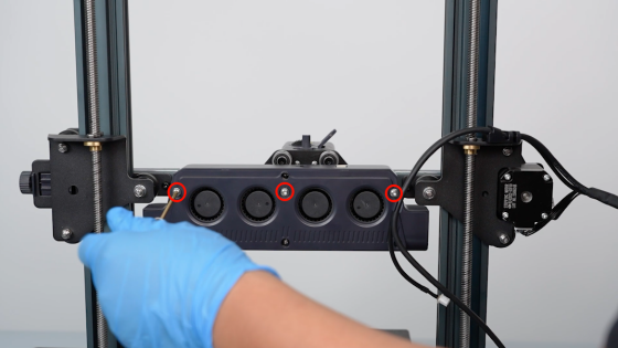
Loosen the three screws securing the rear cooling fan assembly with a 2.5 mm Allen key.
-
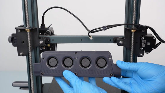
Remove the rear cooling fan assembly.
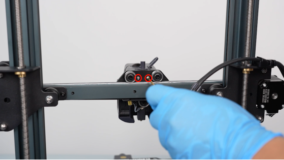
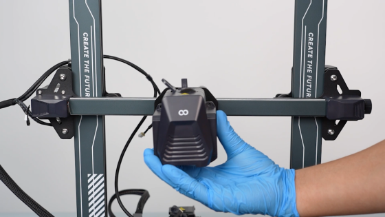
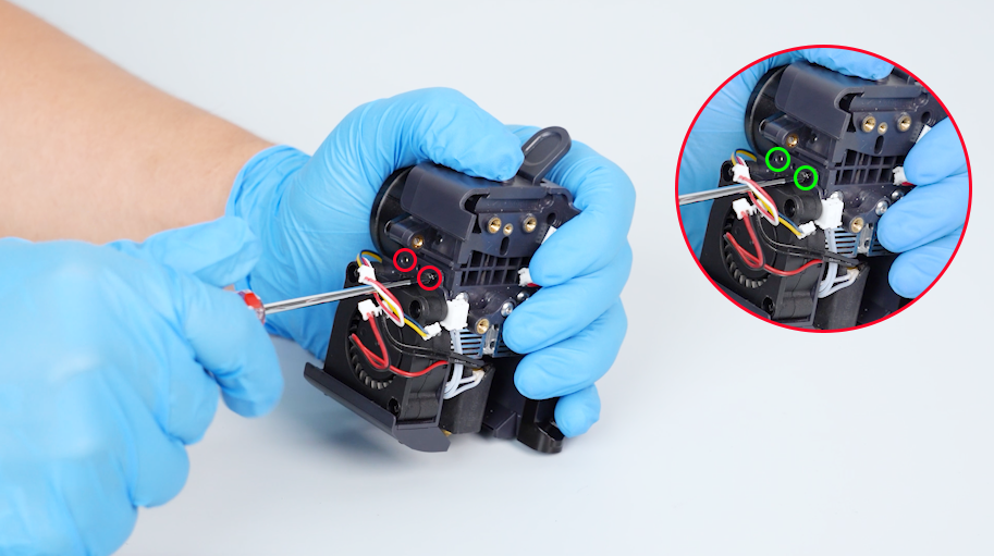
¶ Remove the print head assembly
-
Loosen the two screws securing the connection cable of the print head with a 1.5 mm Allen key.
-
Disconnect the connection cable of the print head.
-
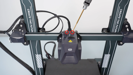
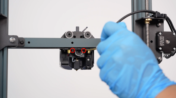
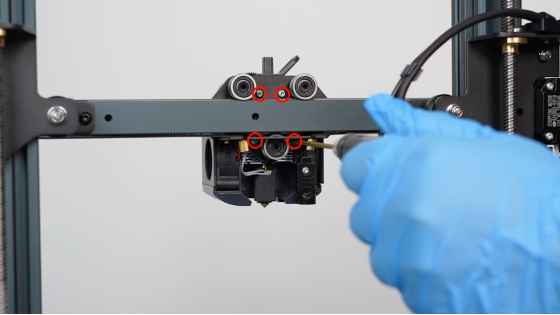
Loosen the four screws securing the back of the print head assembly with a 2.0 mm Allen key.
-
Loosen the two screws securing the front cover of the print head with a 2.0 mm Allen key.
-
Remove the print head assembly.
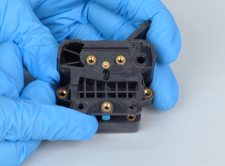
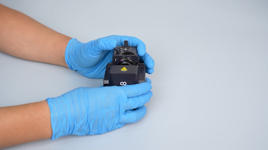
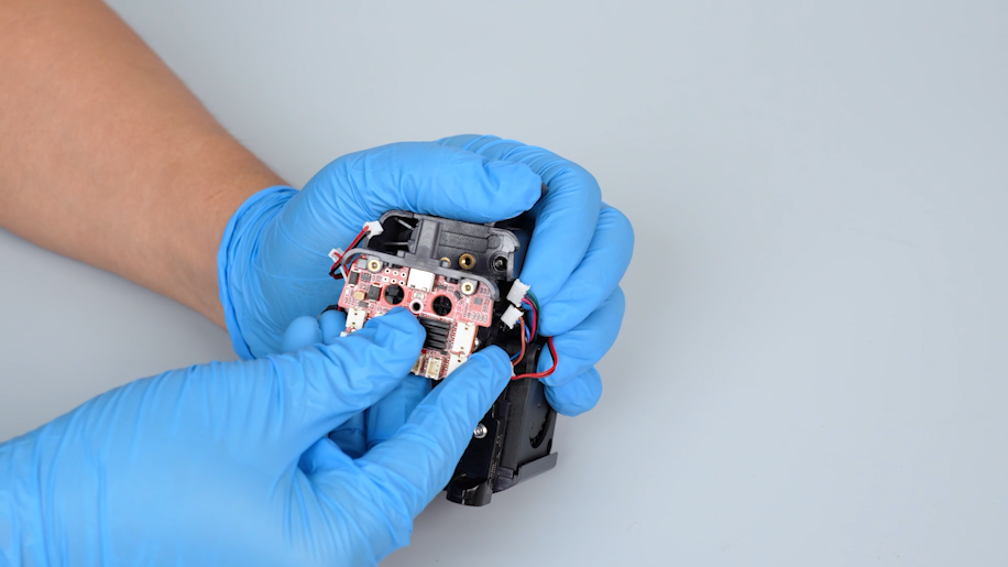
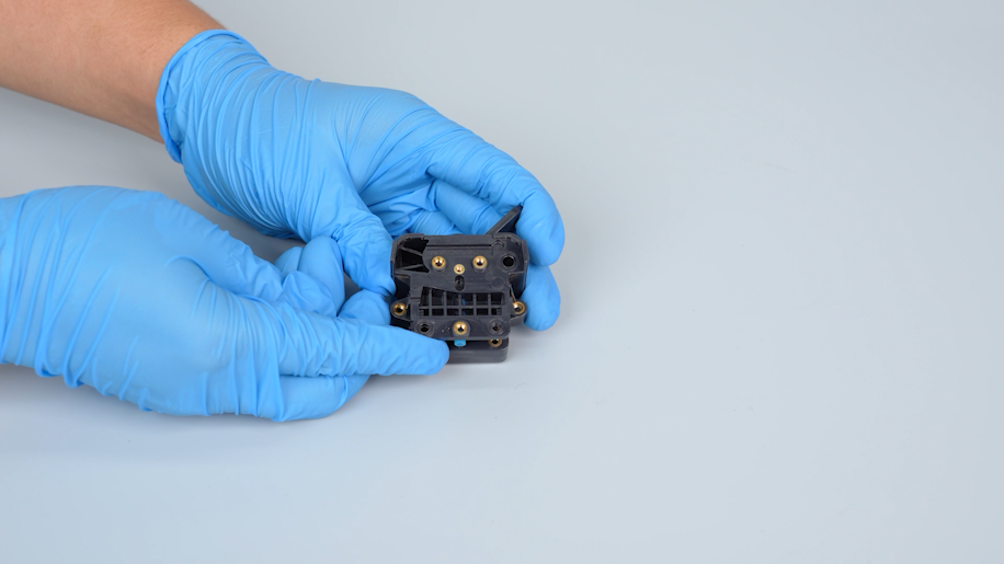
¶ Remove the adapter board of the print head
-
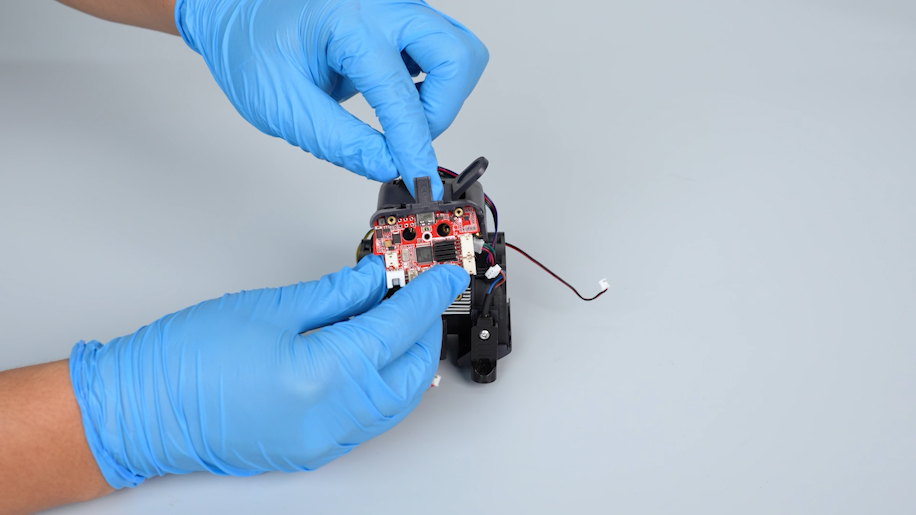
Remove the front cover of the print head.
-
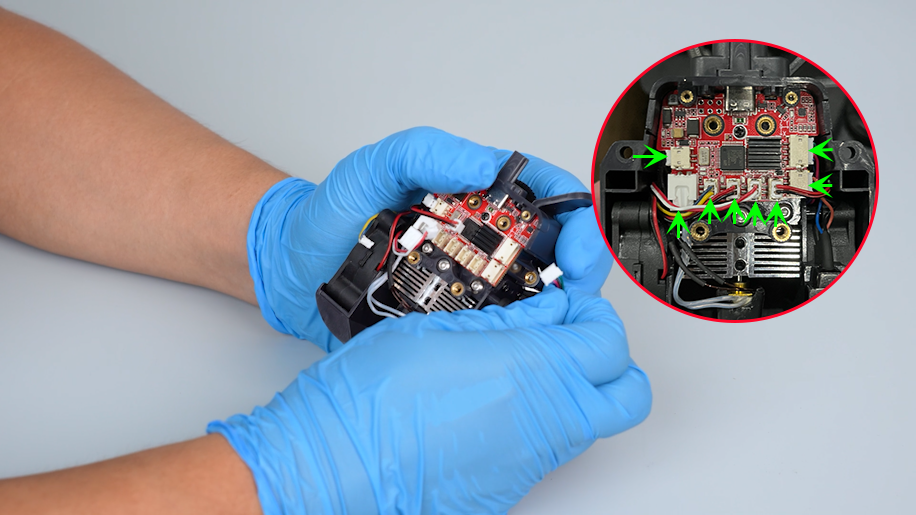
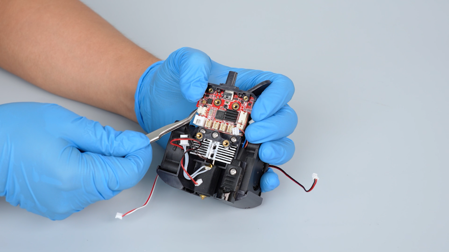
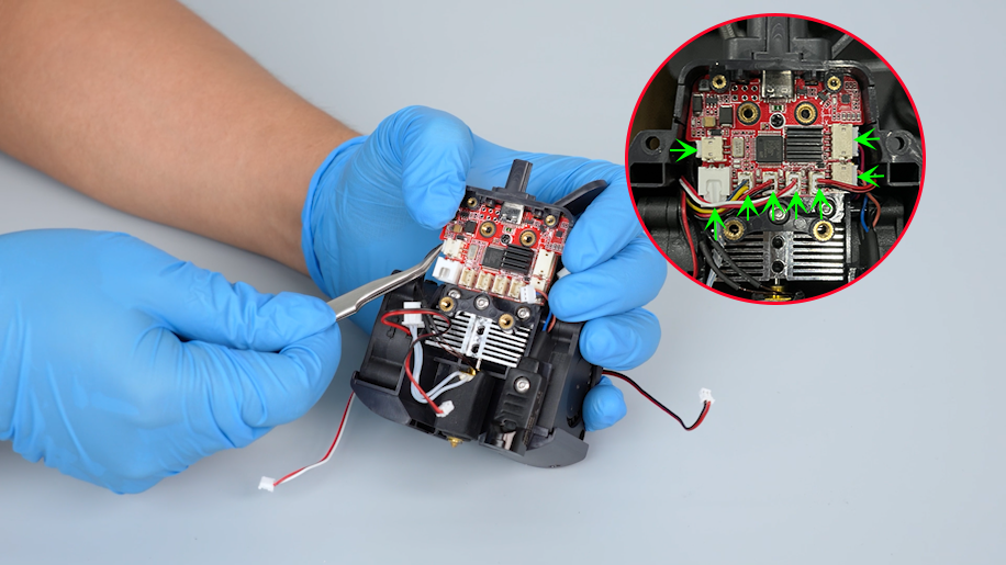
Unplug the cables on the adapter board of the print head.
-
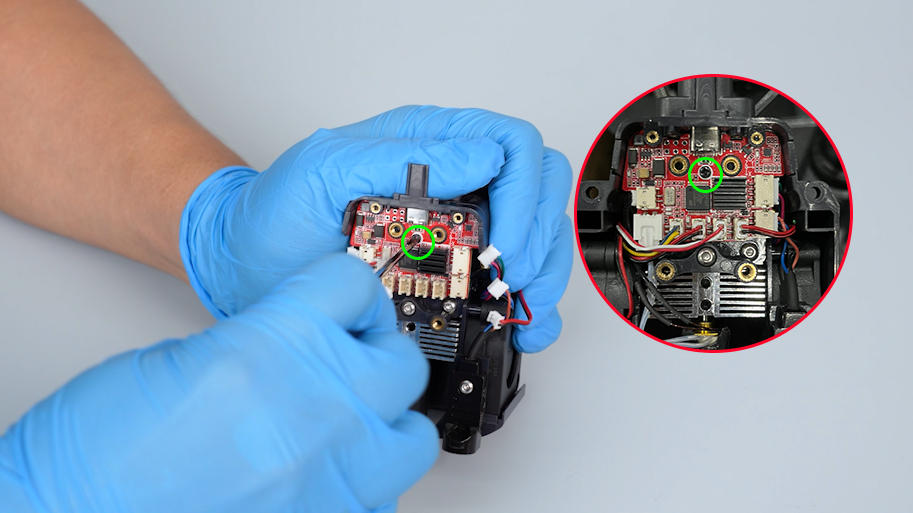
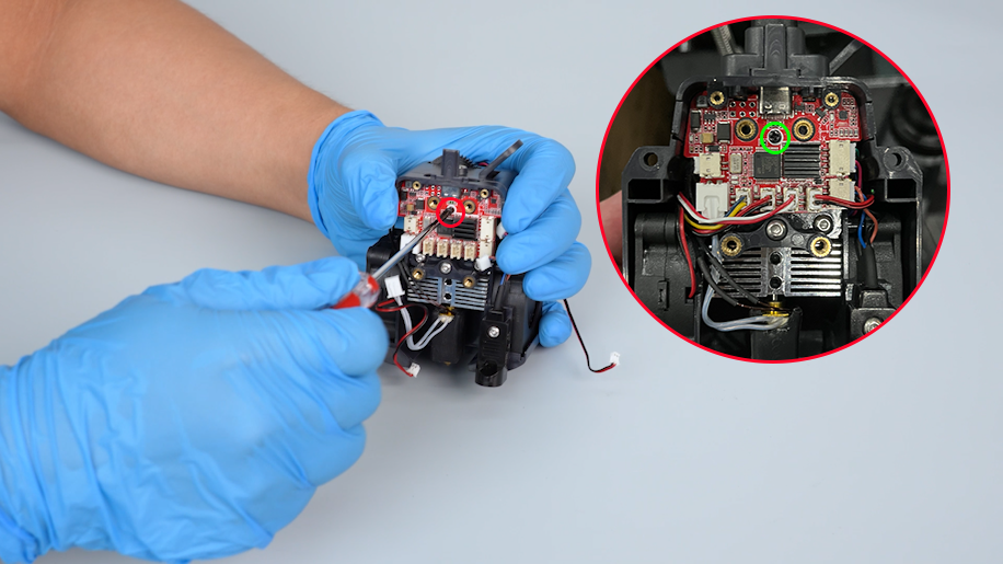
Loosen the screw securing the adapter board of the print head with a Phillips screwdriver.
-
Remove the adapter board of the print head.
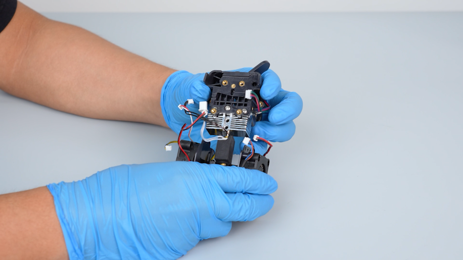
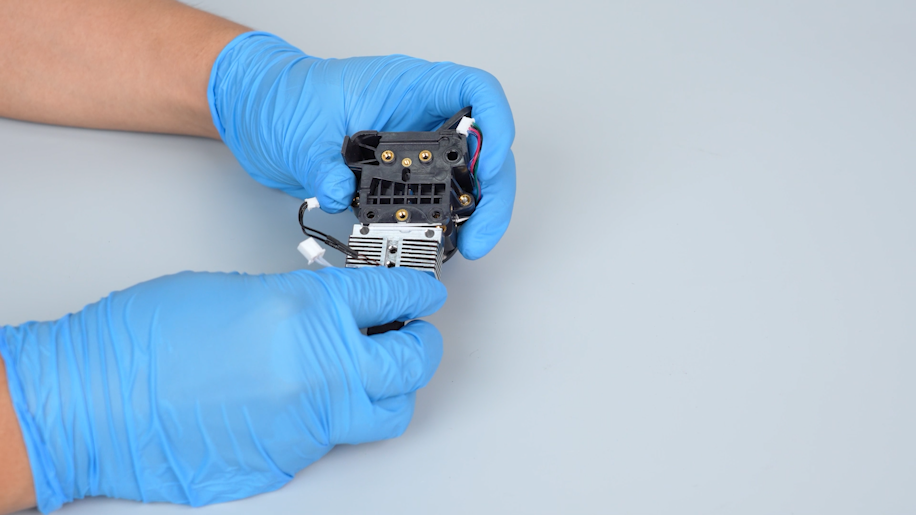
¶ Remove the nozzle assembly
-
Loosen the four screws on the two sides of the model cooling fan support with a Phillips screwdriver.
-
Remove the model cooling fan support.
-
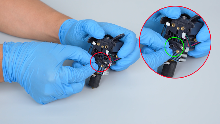
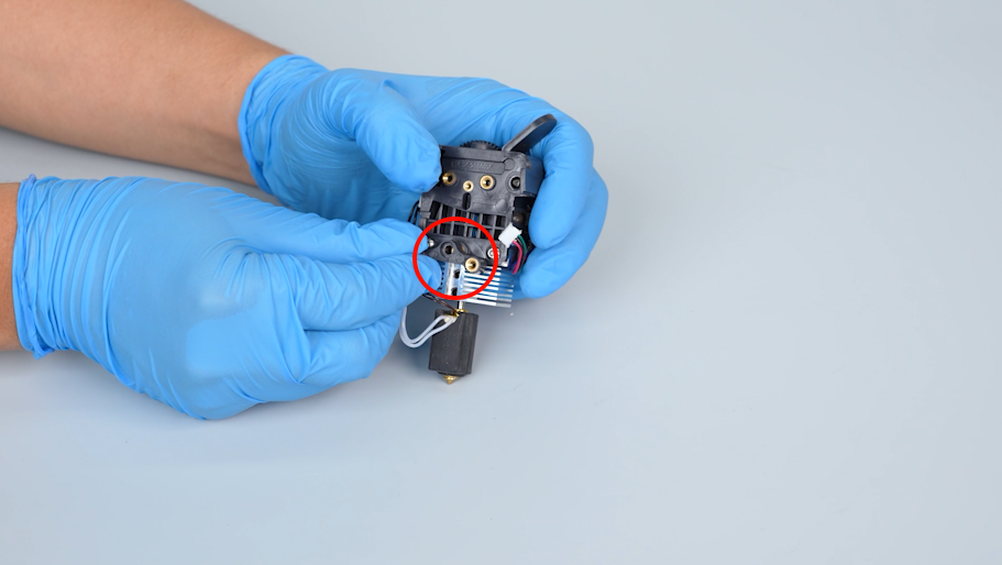
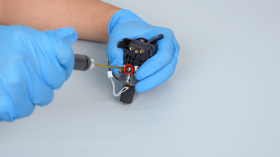
Loosen the screw securing the connection unit with a 2.0 mm Allen key.
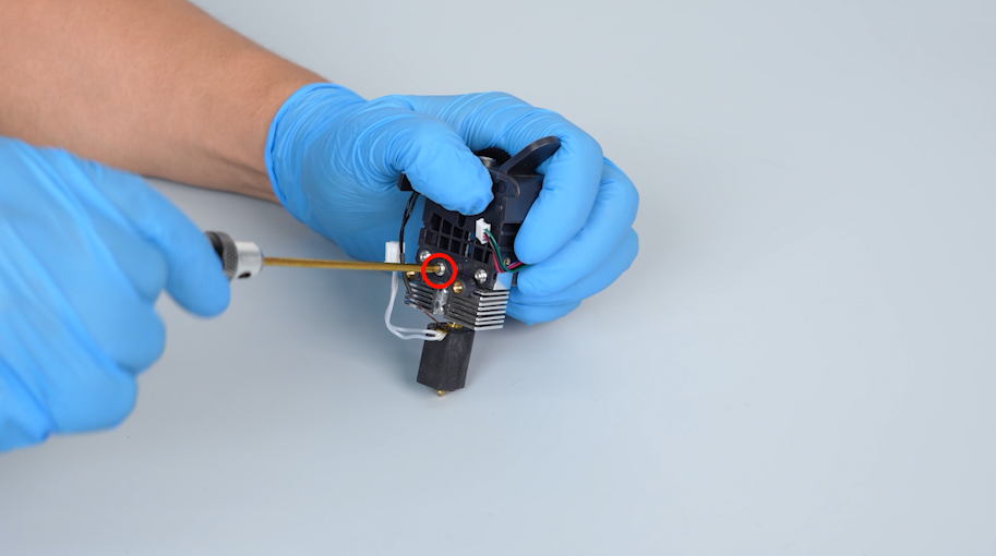
-
Remove the connection unit.
-
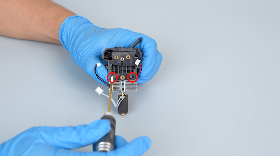
Loosen the two screws securing the nozzle assembly with a 2.0 mm Allen key.
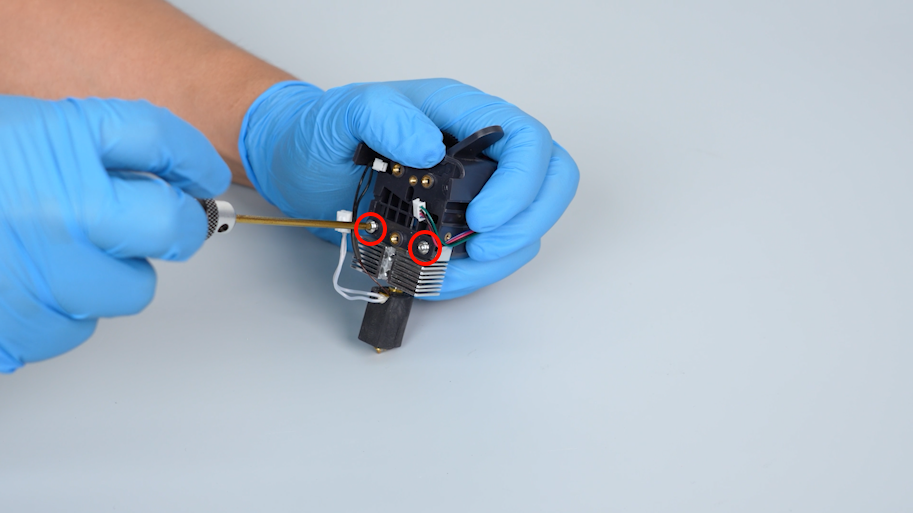
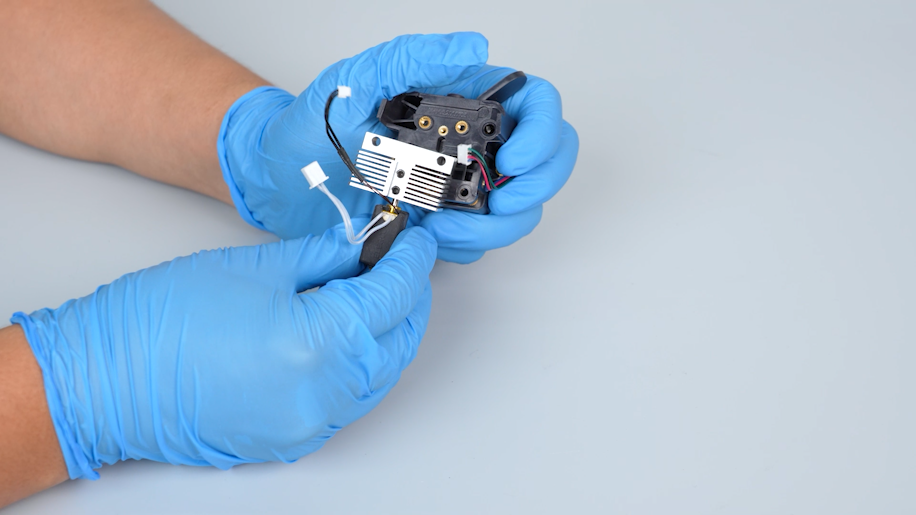
-
Remove the nozzle assembly.
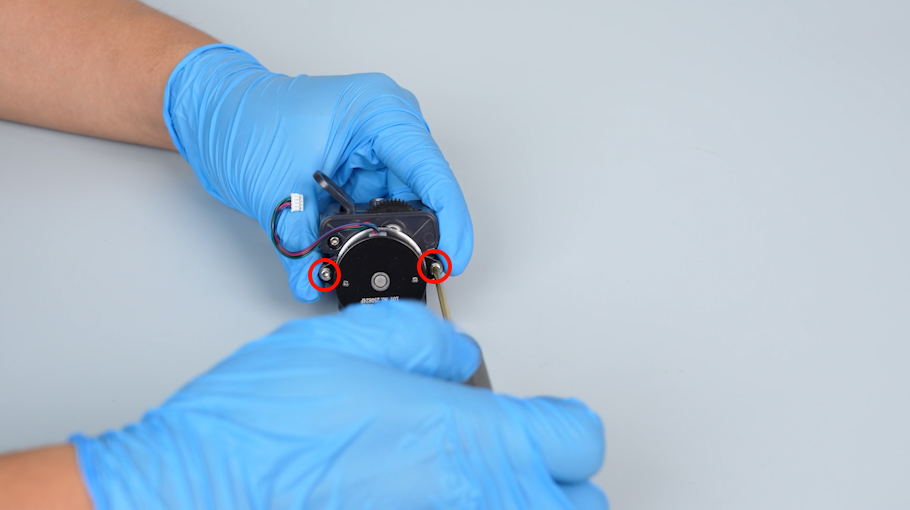
¶ Remove the old gear of the extruder
-
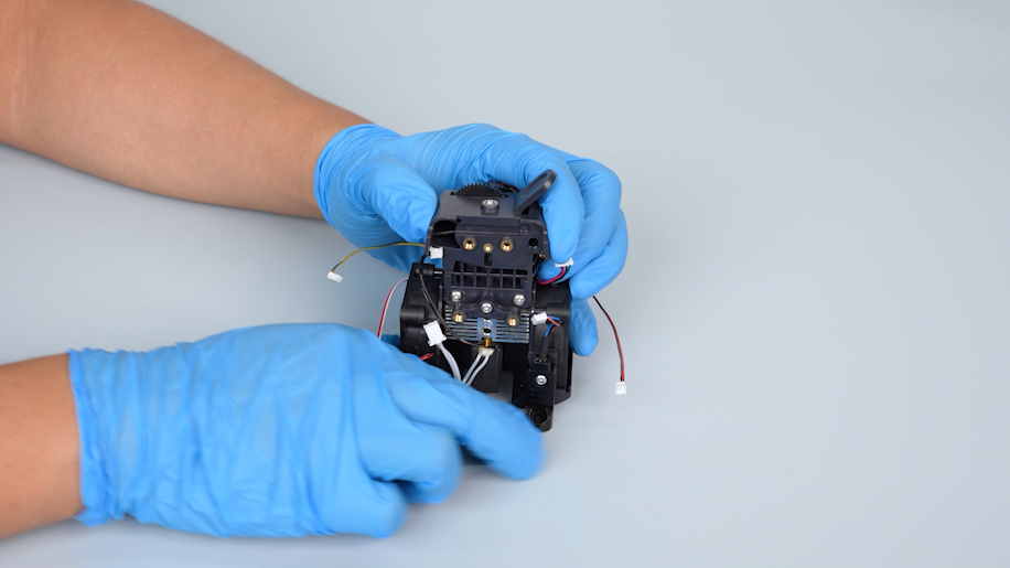
Loosen the two screws securing the extruder motor with a 2.0 mm Allen key.
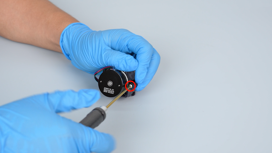
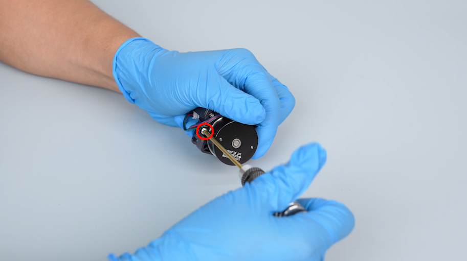
-
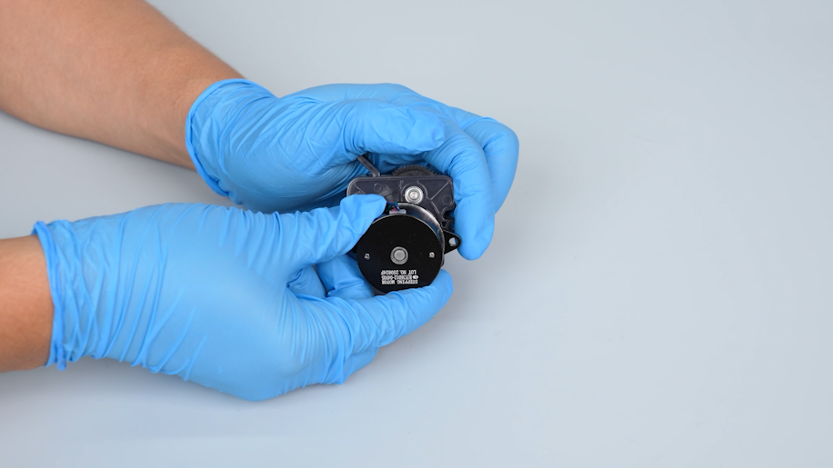
Remove the extruder motor and remove the old extruder gear.
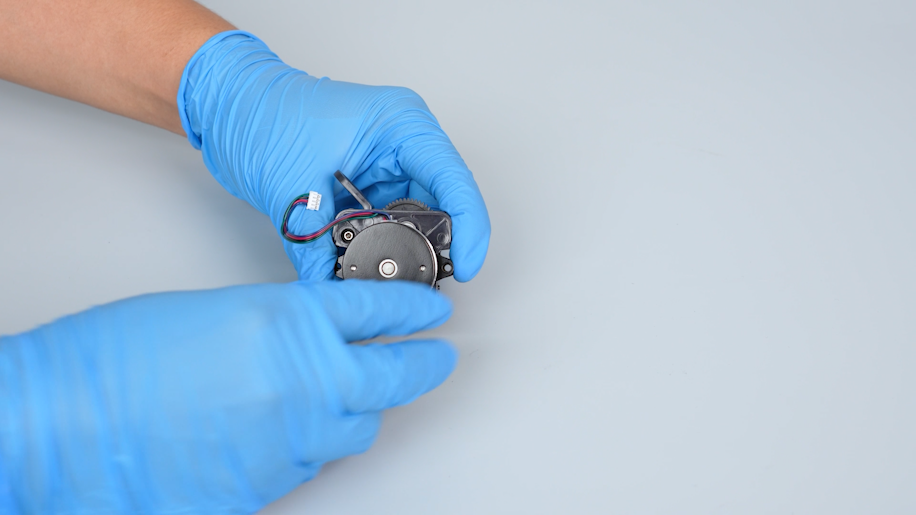
¶ Install a new gear of the extruder
-
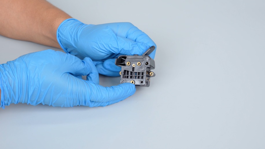
Prepare the new gearbox of the extruder.
-
Prepare the new extruder motor. Align it with the screw holes and put it in the installation position.
- Tighten the two screws securing the extruder motor with a 2.0 mm Allen key.
¶ Install the nozzle assembly
-
Prepare the nozzle assembly. Align it with the screw holes and put it in the installation position.
-
Tighten the two screws securing the nozzle assembly with a 2.0 mm Allen key.
-
Align the connection unit with the screw holes and put it in the installation position. Tighten the screw securing the connection unit with a 2.0 mm Allen key.
-
Align the support of the model cooling fan with the screw holes and put it in the installation position.
-
Tighten the four screws on the two sides of the model cooling fan support with a Phillips screwdriver.
¶ Install the adapter board of the print head
-
Prepare the adapter board of the print head and put it in the installation position.
-
Tighten the screw securing the adapter board of the print head with a Phillips screwdriver.
-
Insert the cables of the thermistor, ceramic heating plate, heat break cooling fan, model cooling fan, nozzle light, proximity switch and the extruder motor on the adapter board of the print head.
-
Organize the cables.
-
Install the front cover of the print head.
¶ Install the print head assembly
-
Prepare the new print head assembly. Align the print head assembly with the screw holes and put it in the installation position.
-
Tighten the two screws securing the front cover of the print head with a 2.0 mm Allen key.
-
Tighten the four screws securing the back of the print head assembly with a 2.0 mm Allen key.
¶ Install the rear cooling fan assembly
-
Prepare the rear cooling fan assembly. Align it with the screw holes and put it in the installation position.
-
Tighten the three screws securing the rear cooling fan assembly with a 2.5 mm Allen key.
-
Plug in the cables of the rear cooling fan assembly.
¶ Verification
-
Plug in the power supply cable and turn the power switch ON (symbol "|").
-
Feed the filament into the extruder.
-
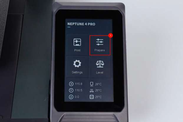
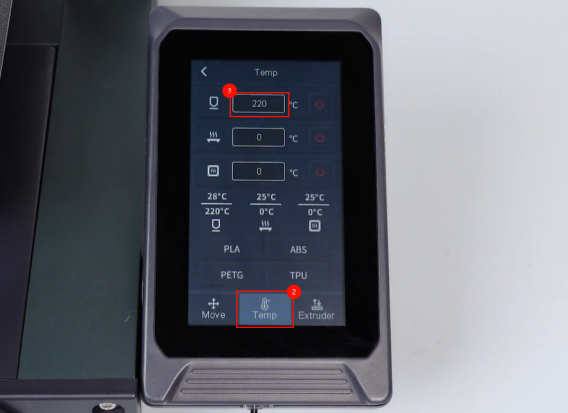
On the touch screen, select Prepare - Temperature. Set the temperature of the nozzle to 220 ℃.
-
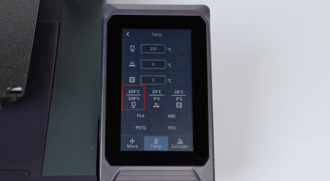
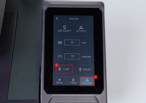
After the nozzle heating to the set temperature, click Extruder - Load.
-
Observe that the filament is extruded normally from the nozzle. The printer is ready for use after it is re-leveled.