¶ Tools and Materials
-
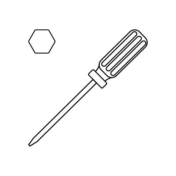
A 1.5 mm Allen key
-
A 2.0 mm Allen key
-
A 2.5 mm Allen key
-
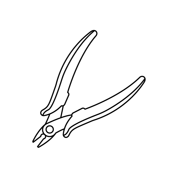
A pair of pliers
-
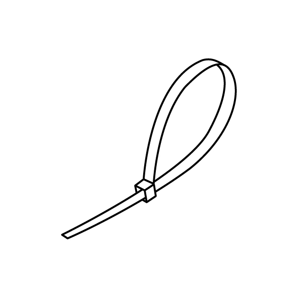
Cable ties
-
A new extruder communication cable
¶ Instruction
¶ Preparation
Turn the power switch OFF (symbol "〇") and unplug the power supply cable.
¶ Remove the old extruder communication cable
-
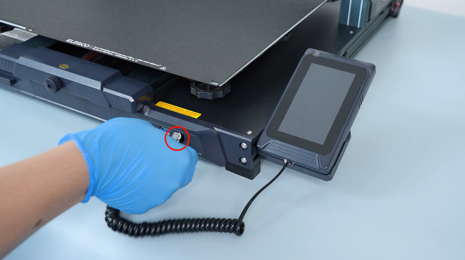
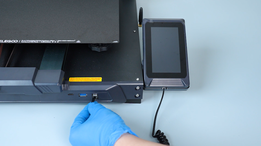
Disconnect the touch screen wire and remove the touch screen.

-
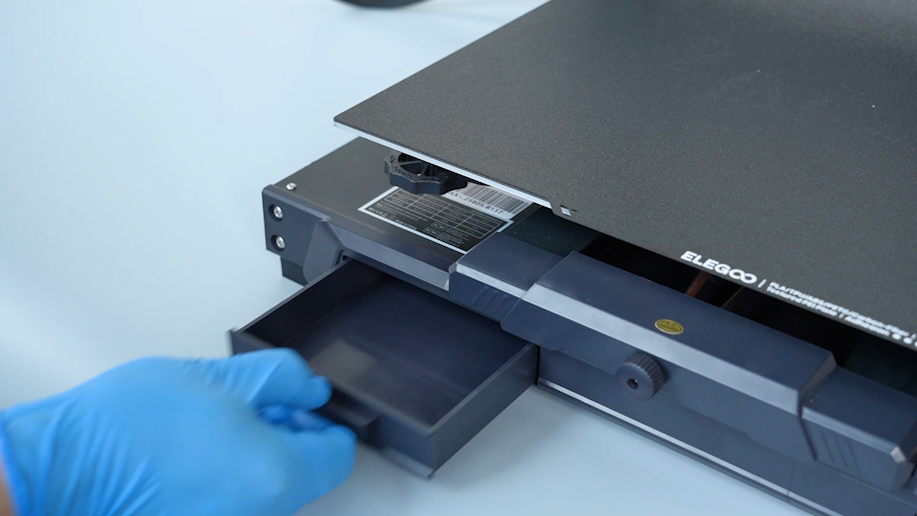
Remove the tool drawer.
-
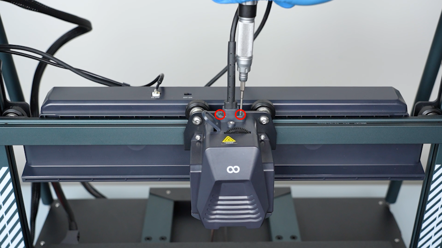
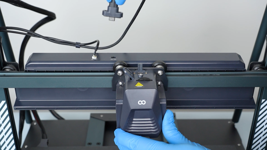
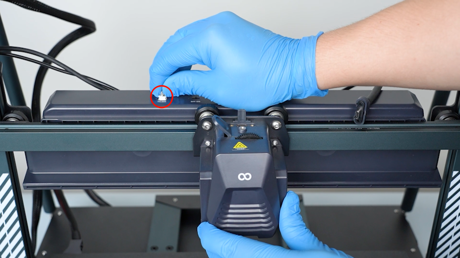
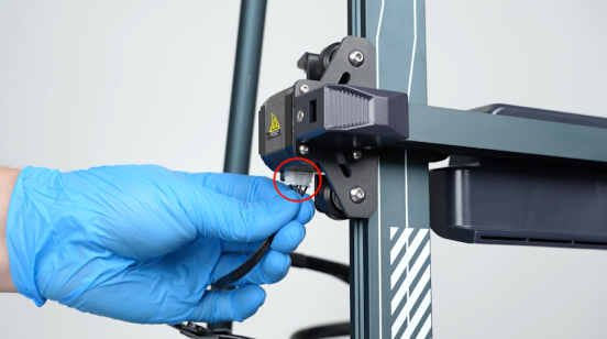
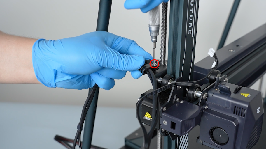
Loosen the two screws securing the extruder communication cable with a 1.5 mm Allen key. Unplug the extruder communication cable.
-
Unplug the auxiliary cooling fan cable.
-
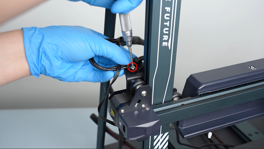
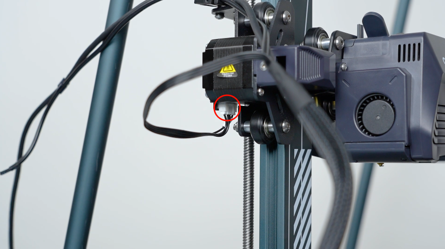
Loosen the screw securing the cable clip with a 2.5 mm Allen key.
-
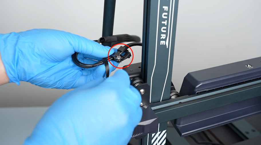
Unplug the X-axis motor cable.
-
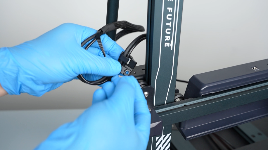
Remove the clip.
-
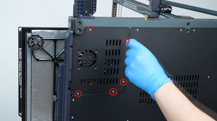
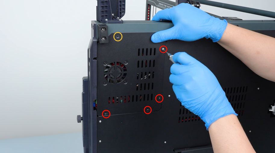
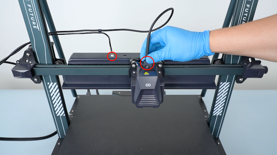
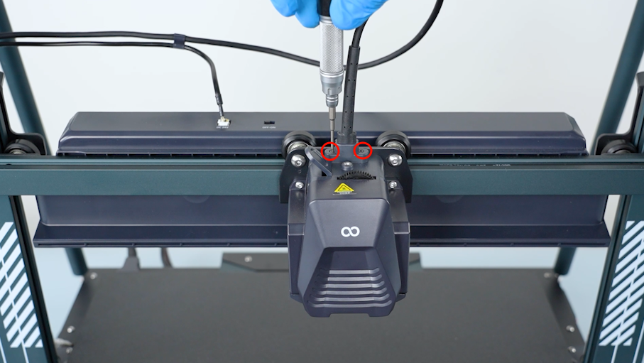
Release and remove the screws securing the motherboard cover with a 2.0 mm Allen key.
-
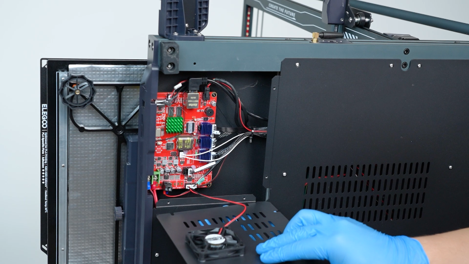
Remove the bottom cover carefully. Unplug the cable of the motherboard cooling fan.
-
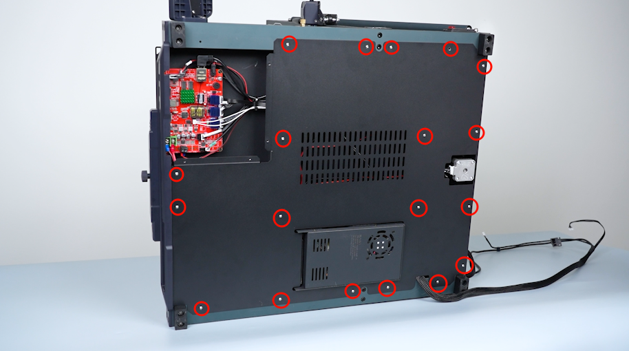
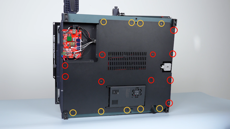
Release and remove the screws securing the bottom cover with a 2.0 mm Allen key. Hold the bottom cover and remove it.
-
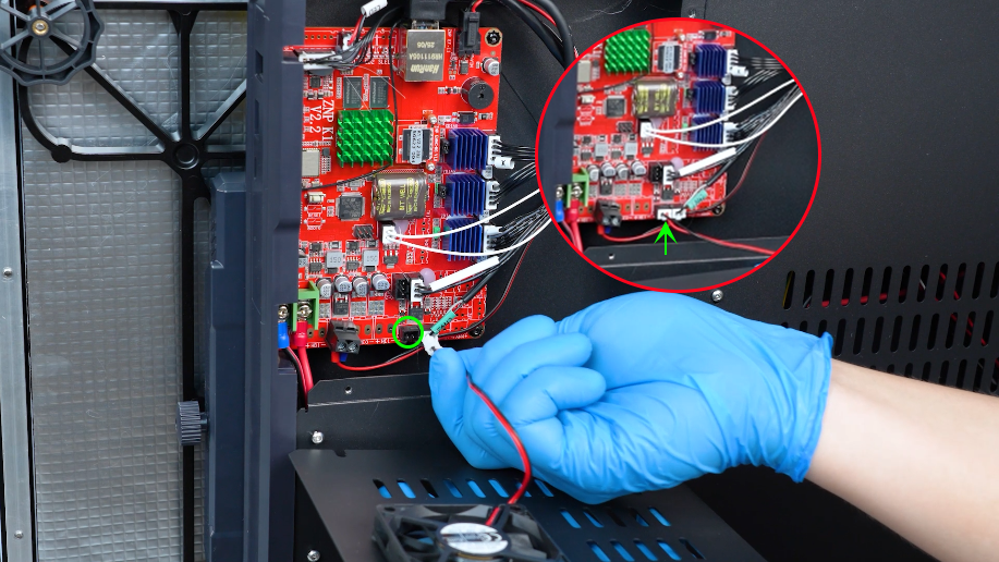
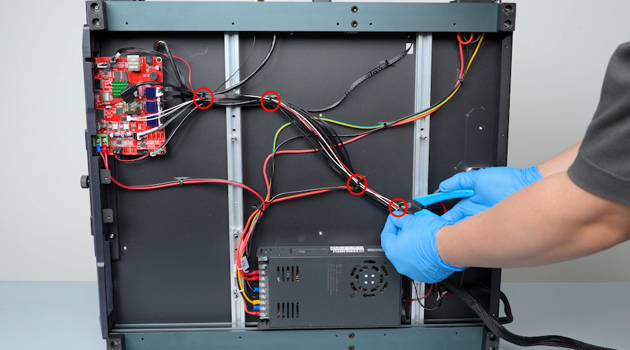
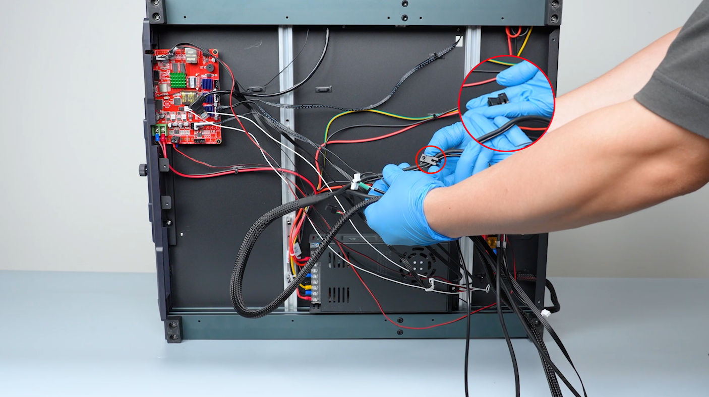
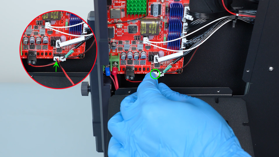
Remove the plugs of the extruder communication cable.
-
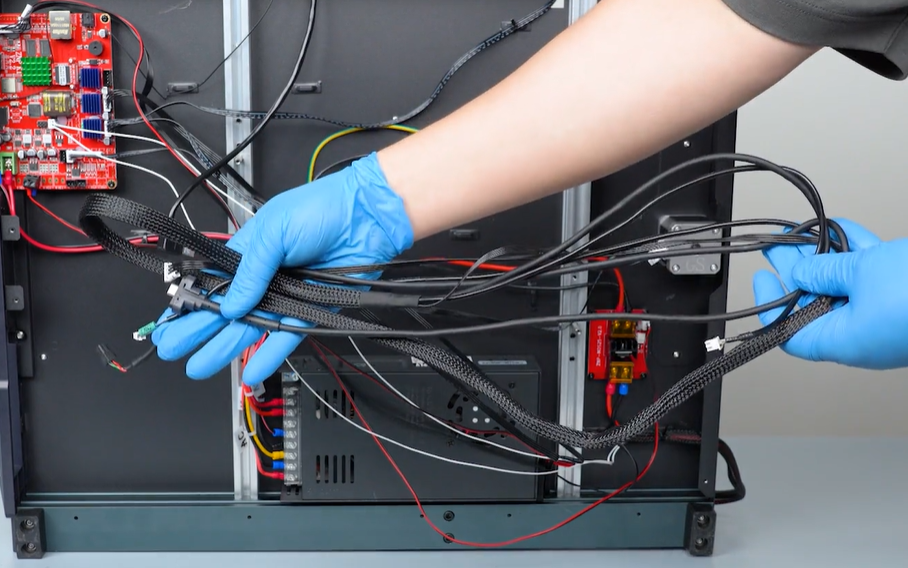
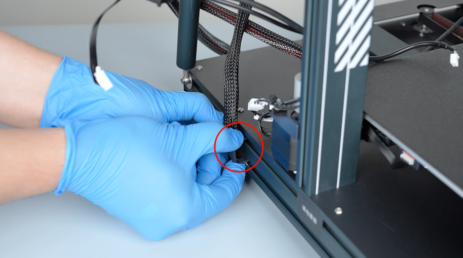
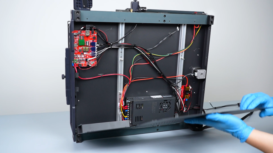
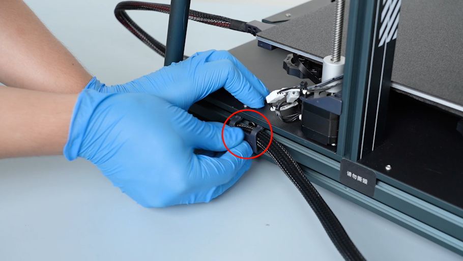
Cut off the cable ties with a pair of pliers. Remove the old extruder communication cable and the clip.
¶ Install the new extruder communication cable
-
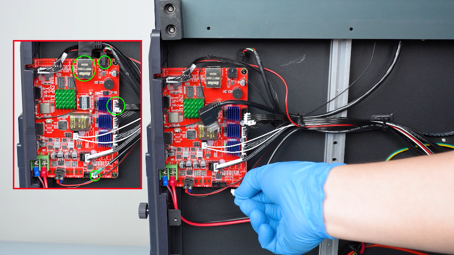
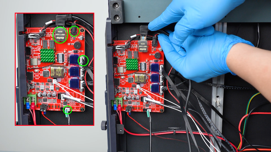
Insert the plugs of the extruder communication cable onto the ports on the motherboard.
-
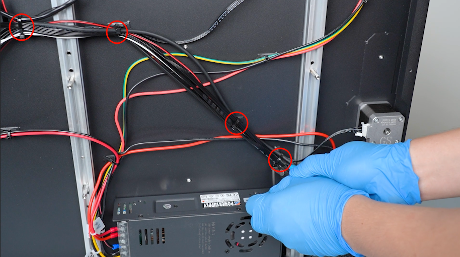
Organize the cables. Secure the cables with the chamber clips with cable ties. Cut off the ends of the cable ties.
-
Get the bottom cover. Tighten the screws securing the bottom cover with a 2.0 mm Allen key.
Note: Screws labeled by the yellow circle are M3 x 16, and screws labeled by the red circle are M3 x 6.
-
Get the motherboard cover. Plug in the motherboard cooling fan cable.
-
Install the motherboard cover and hold the cover. Tighten the screws securing the motherboard cover with a 2.0 mm Allen key.
Note: Screw labeled by the yellow circle is M3 x 16, and screws labeled by the red circle are M3 x 6.
-
Install the clip.
-
Install the extruder communication cable with the clip and tighten the screw securing the clip with a 2.5 mm Allen key.
-
Insert the X-axis motor plug.
-
Insert the plugs of the auxiliary cooling fan cable and the extruder communication cable.
-
Tighten the two screws securing the extruder communication cable with a 1.5 mm Allen key.
-
Put the touch screen on the bracket and plug in the connection wire.
¶ Verification
-
Plug in the power supply cable. Turn the power switch ON (symbol "|") .
-
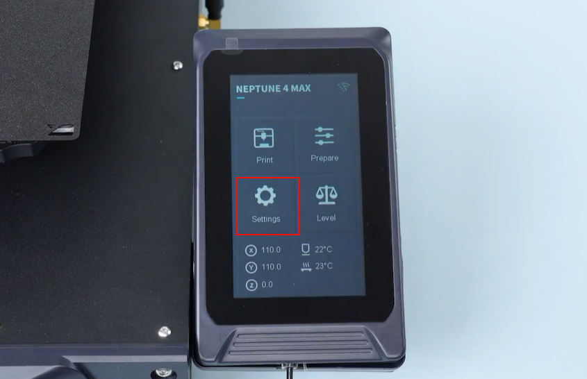
Check that all functions of the extruder communication cable are working properly on the touch screen.
-
Confirm that the touch screen works normally. The printer is ready for use.
.png)
.png)