¶ Tools and Material
-
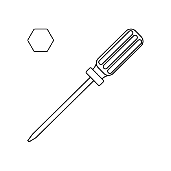
A 2.0 mm Allen key
-
A new servomotor
-
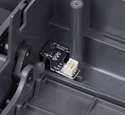
A new servomotor detection board
¶ Instruction
¶ Preparation
-
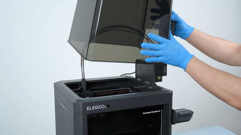
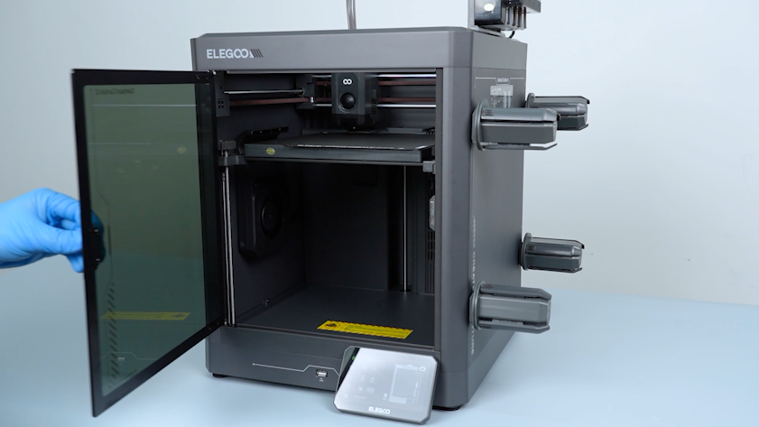
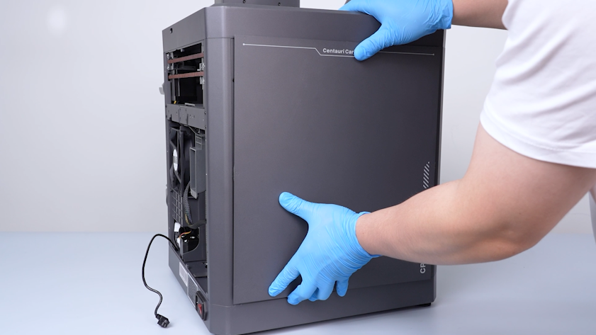
Remove the lid.
-
Plug in the power supply cable. Turn the power switch ON (symbol "|").
-
Open the front glass door.
-
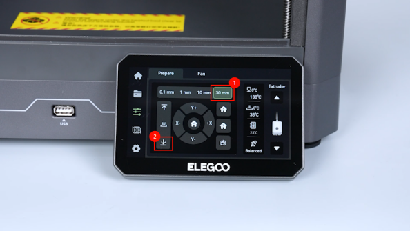
On the touch screen, select Control - Homing.
-
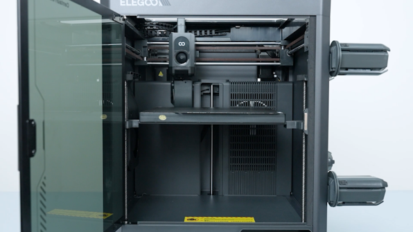
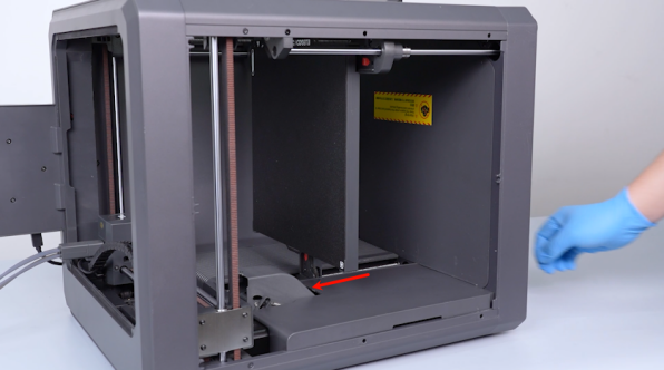
After the homing process, select 30 mm - ↓ to lower the heated bed by 60 mm on the touch screen.
-
Turn the power switch OFF (symbol "〇"). Unplug the power supply cable.
¶ Remove the back cover and bottom cover
-
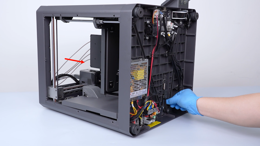
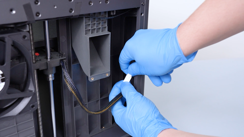
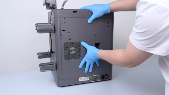
Unplug the communication cable of the CANVAS.
-
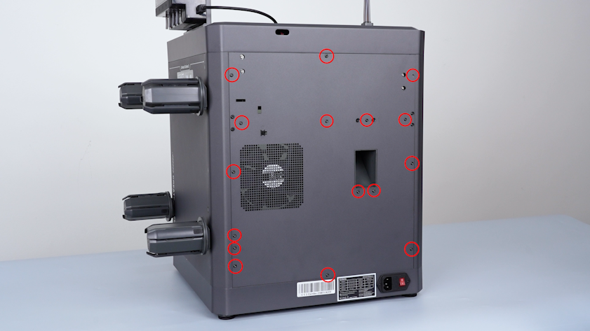
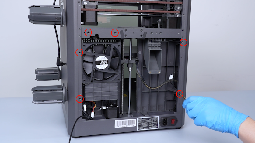
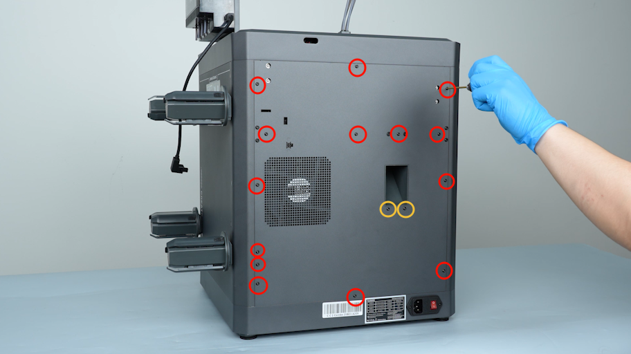
Release and remove the sixteen screws securing the back cover with a 2.0 mm Allen key.
-
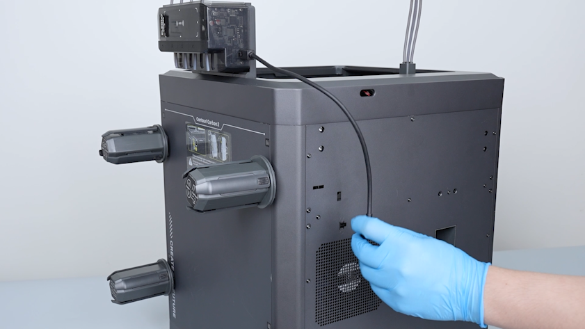
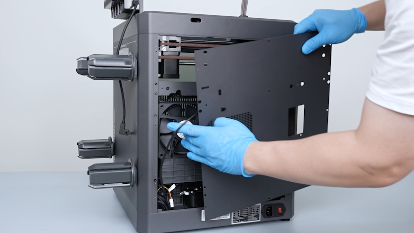
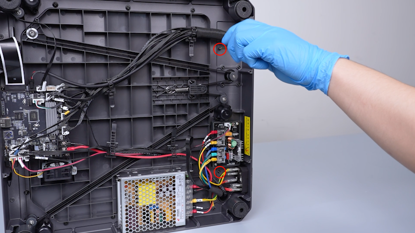
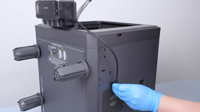
Remove the CANVAS extension cable from the gap on the chamber cooling fan side.
-
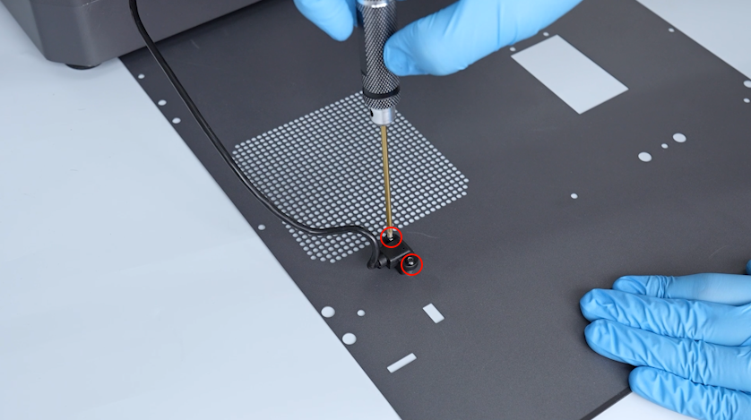
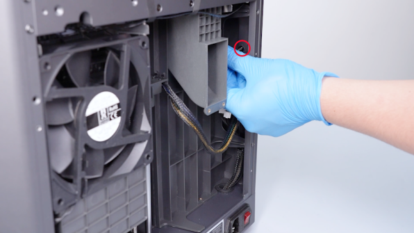
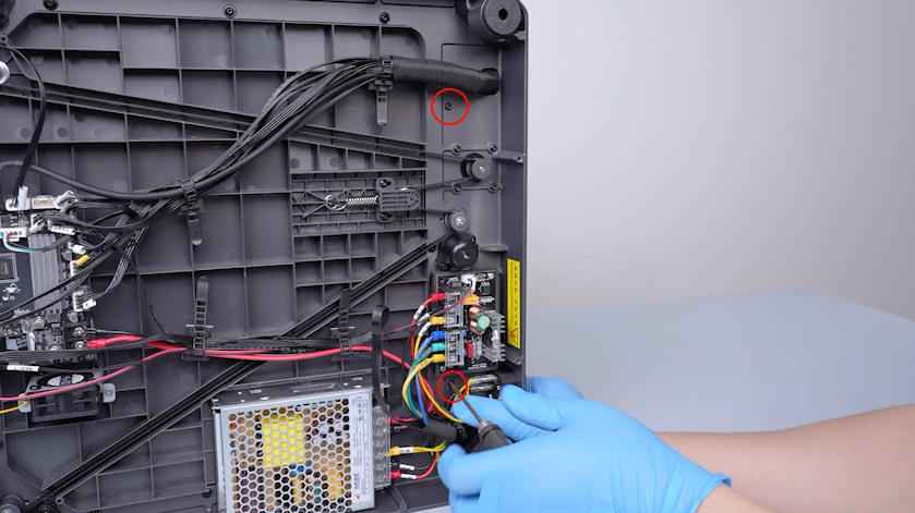
Lay the back cover flat on the table. Release and remove the two screws securing the adapter cable of the CANVAS with a 2.0 mm Allen key.
-
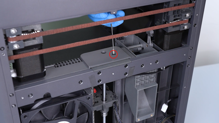
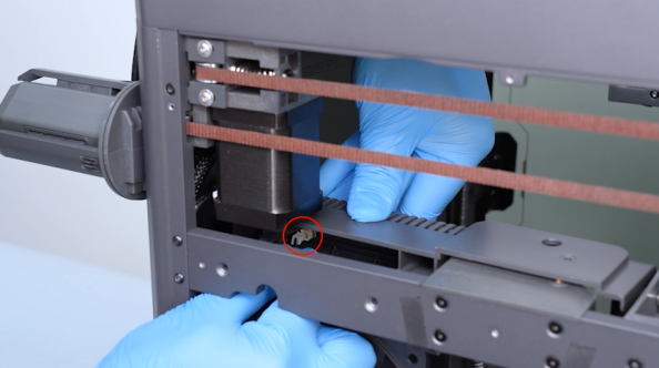
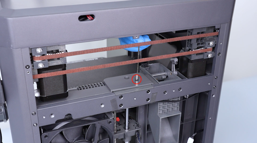
Release and remove the screw on the partition with a 2.0 mm Allen key.
-
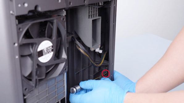
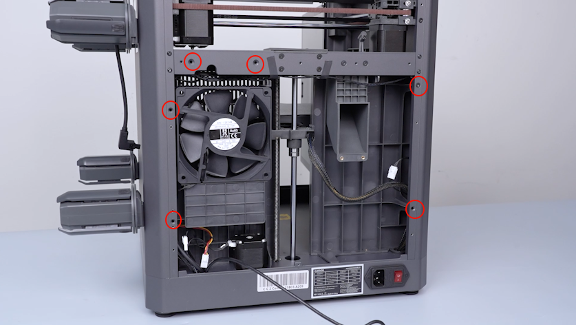
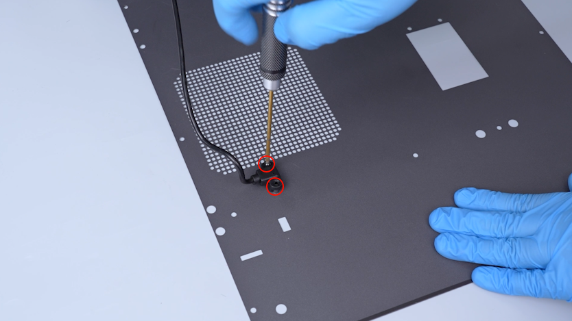
Release and remove the six screws on the back side of the partition with a 2.0 mm Allen key.
-
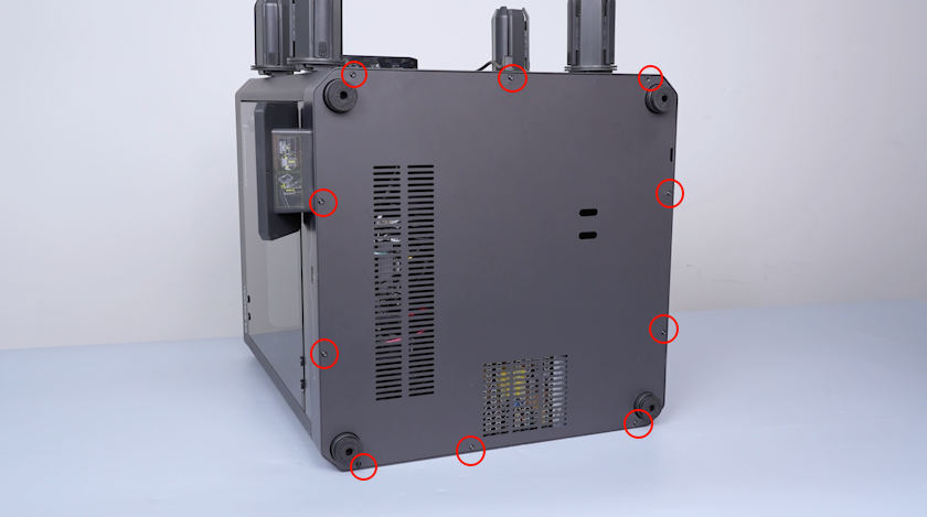
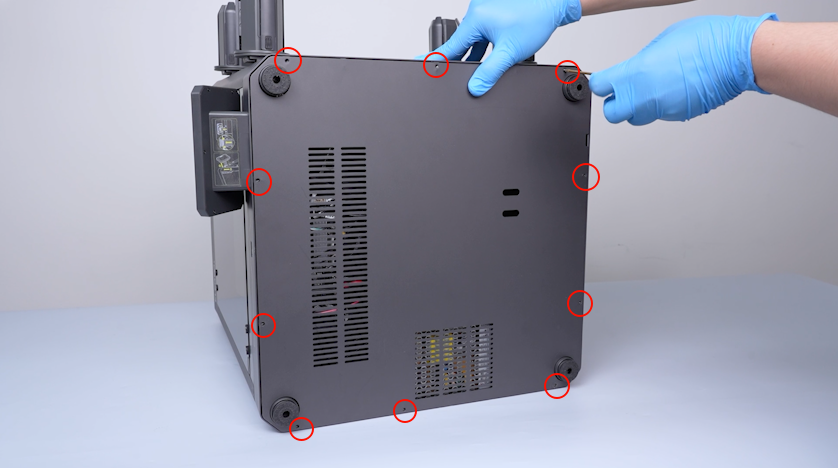
Release and remove the ten screws securing the bottom cover with a 2.0 mm Allen key. Remove the bottom cover.
¶ Remove the left-side cover and partition
-
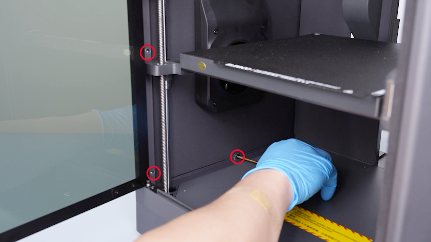
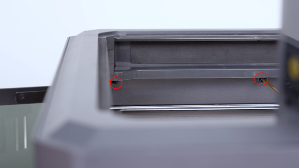
Release and remove the two screws securing the bottom of the partition with a 2.0 mm Allen key.
-
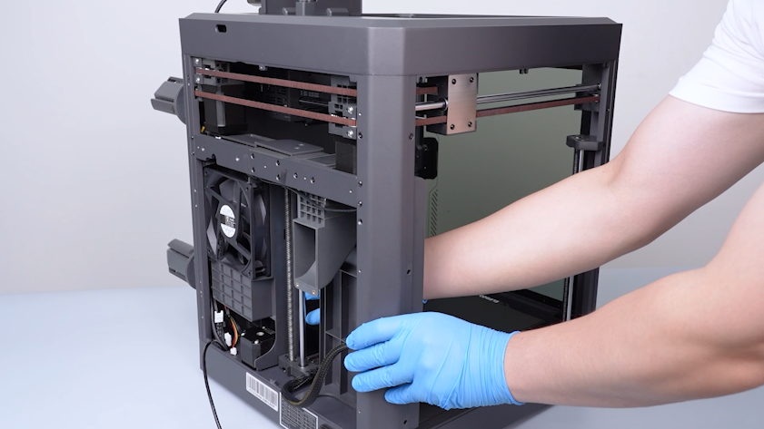
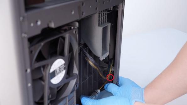
Unplug the auxiliary cooling fan cable.
-
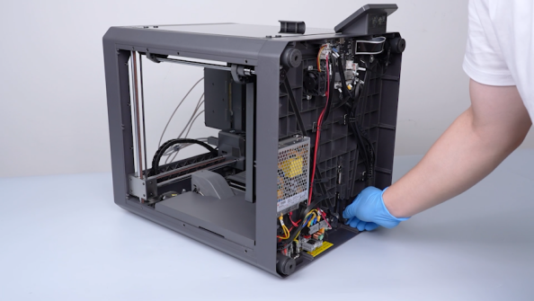
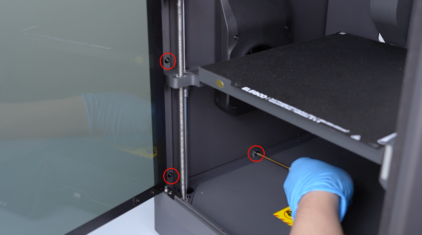
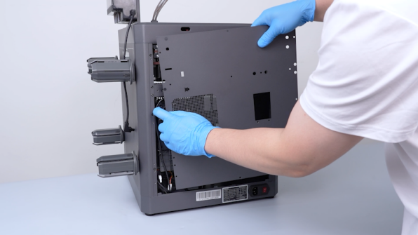
Release and remove the two screws on the back of the left-side cover with a 2.0 mm Allen key.
-
Release and remove the three screws on the upper of the left-side cover with a 2.0 mm Allen key.
-
Release and remove the three screws on the front of the left-side cover and the bottom of the left-side cover with a 2.0 mm Allen key.
-
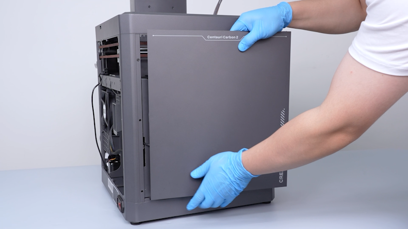
Remove the left-side cover.
-
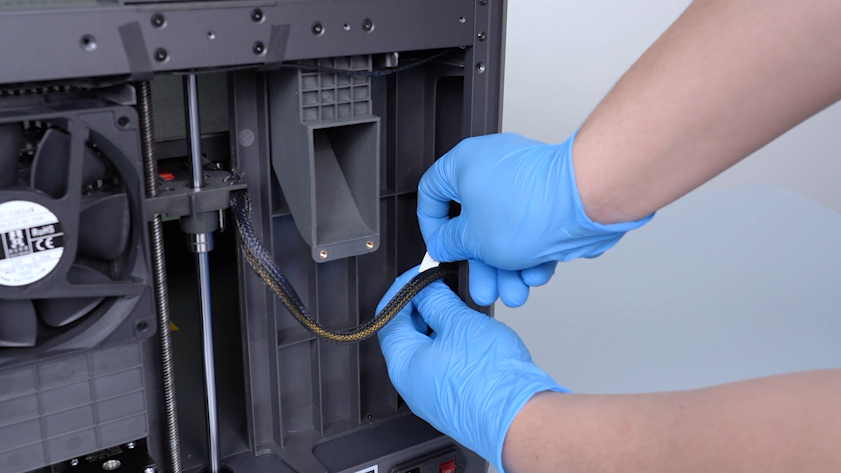
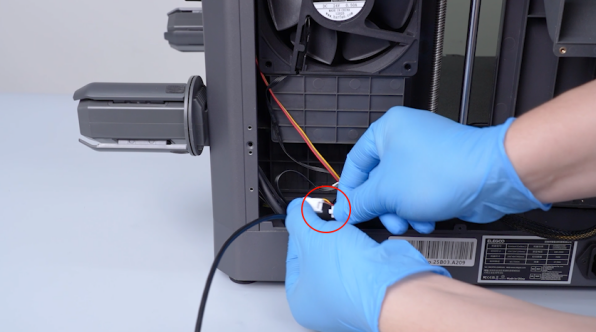
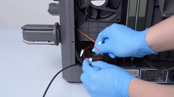
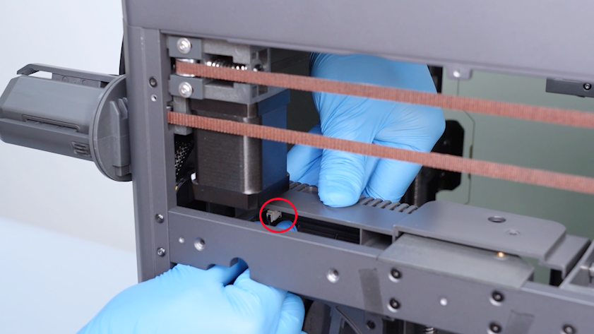
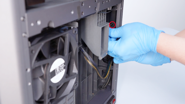
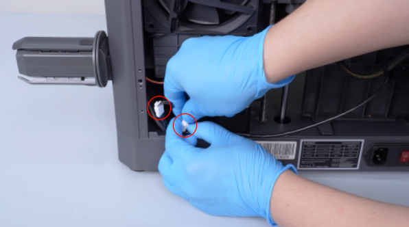
Unplug the servomotor adapter cable and the chamber cooling fan cable.
-
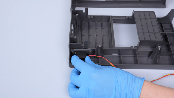
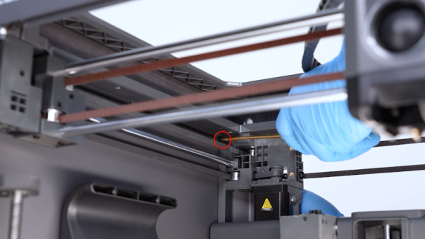
Unplug the servomotor cable.
-
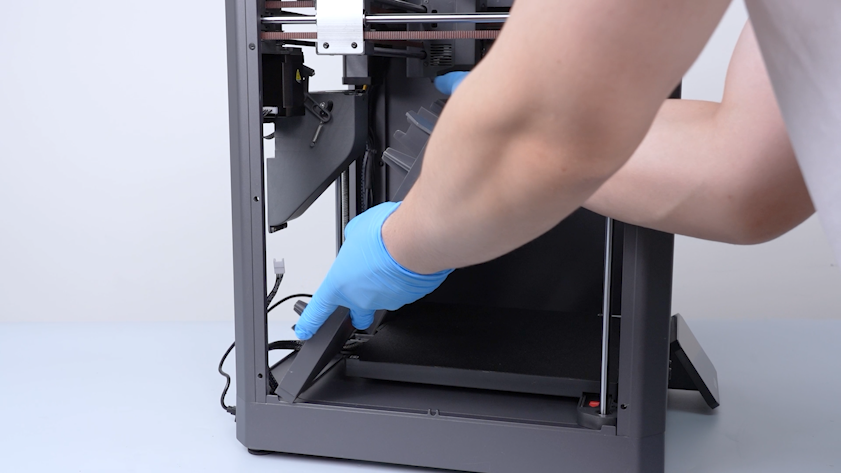
Pull the Z-axis timing belt to lower the heated bed to the bottom of the printer.
-
Remove the partition.
¶ Replace the servomotor
¶ Remove the old servomotor
-
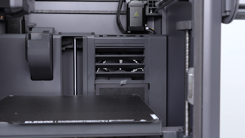
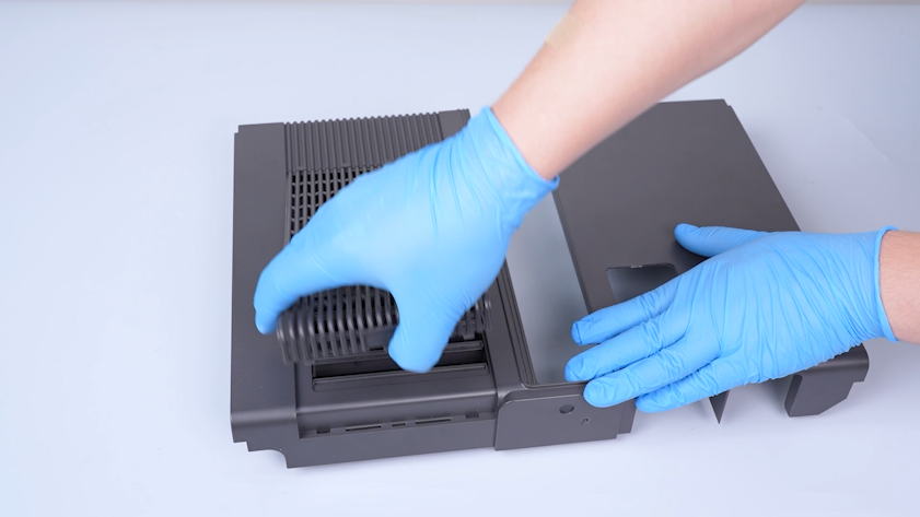
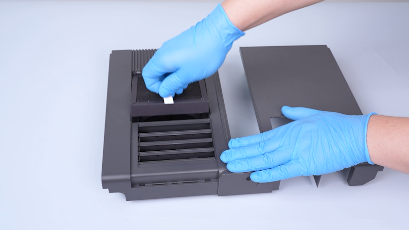
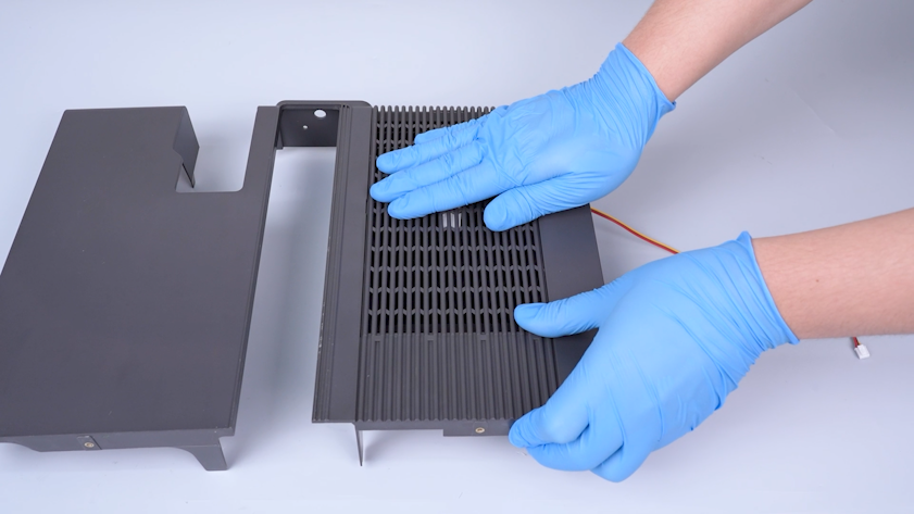
Remove the grating cover and the filter.
-
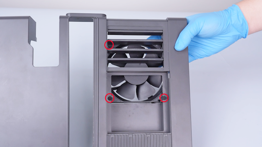
Remove the three mounting snaps.
-
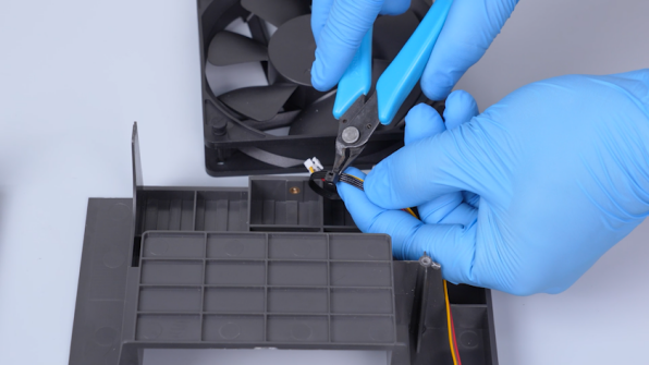
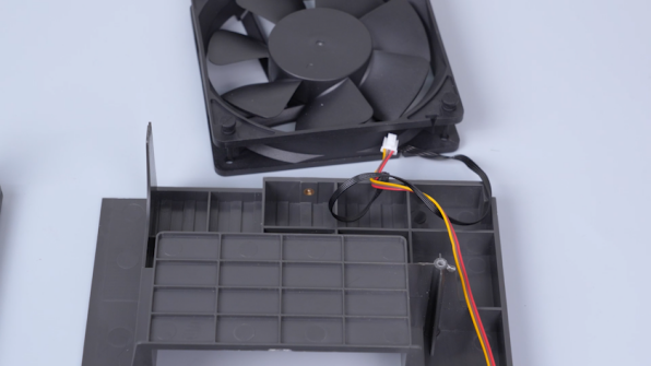
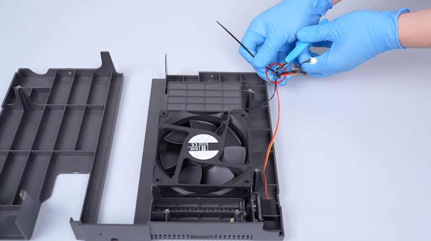
Cut off the cable ties with a pair of pliers. Remove the chamber cooling fan.
-
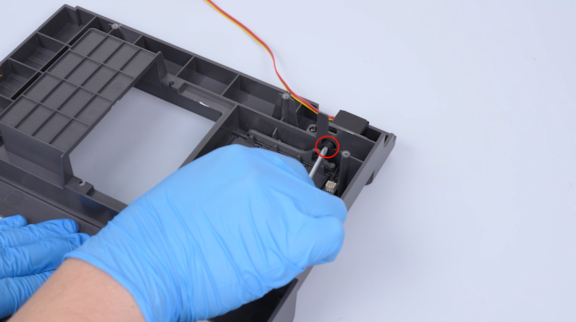
Release and remove the screw securing the servomotor with a Phillips screwdriver.
-
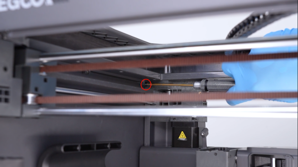
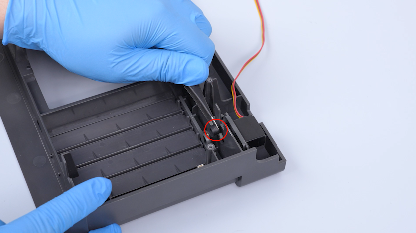
Release and remove the screws securing the servomotor swing arm with a 2.0 mm Allen key.
-
Remove the servomotor swing arm with a pair of tweezers.
-
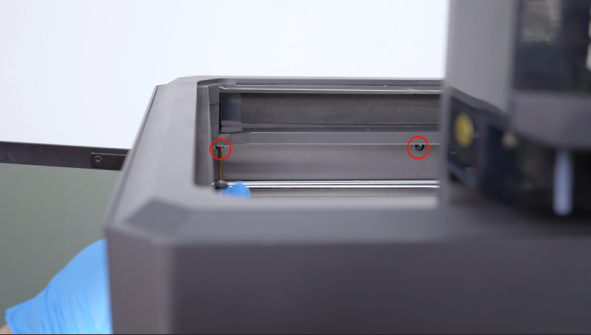
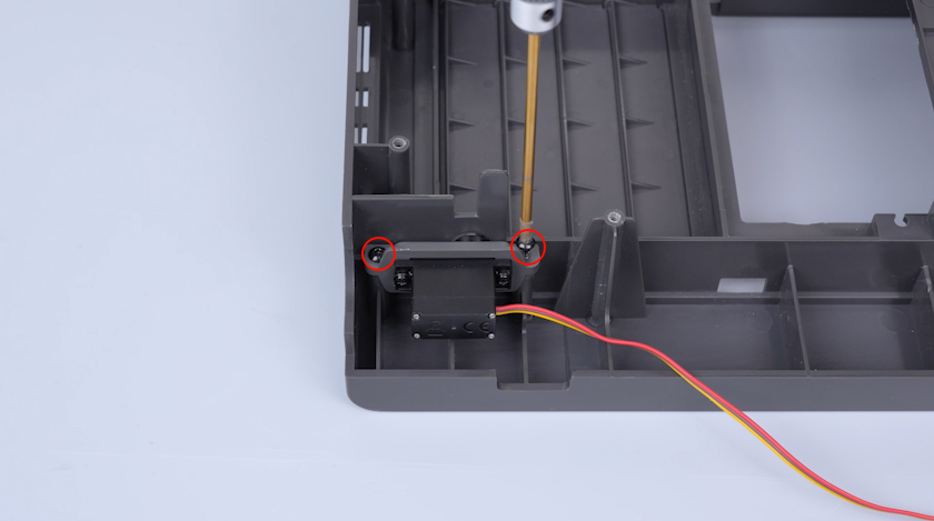
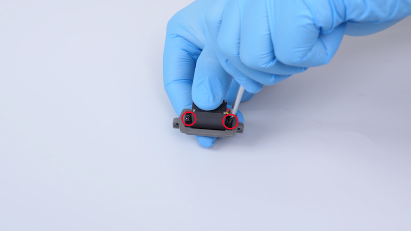
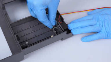
Release and remove the two screws securing the servomotor holder with a 2.0 mm Allen key.
-
Release and remove the two screws securing the back side of the holder with a Phillips screwdriver.
-
Remove the old servomotor.
¶ Install the new servomotor
-
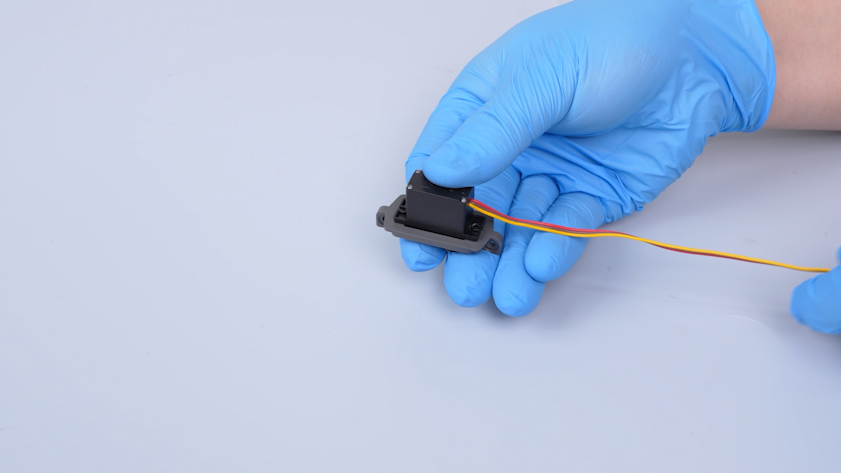
Put the new servomotor in the installation position.
-
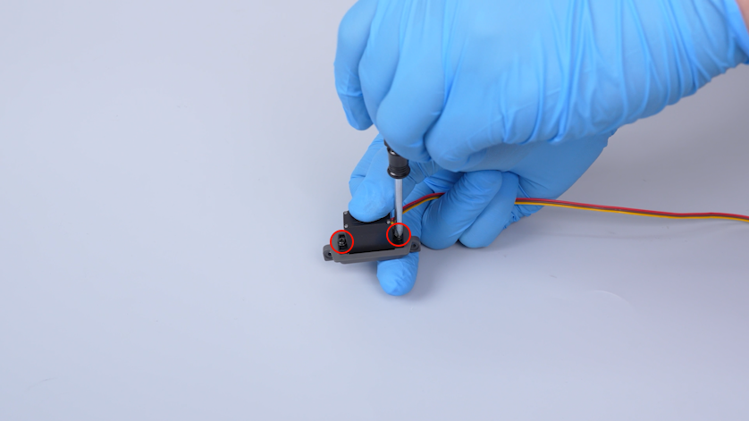
Tighten the two screws securing the back side of the holder with a Phillips screwdriver.
-
Put the servomotor in its installation position of the partition. Tighten the two screws.
-
Put the swing arm in the installation position. Tighten the two screws securing the swing arm.
¶ Replace the servomotor detection board
¶ Remove the old servomotor detection board
-
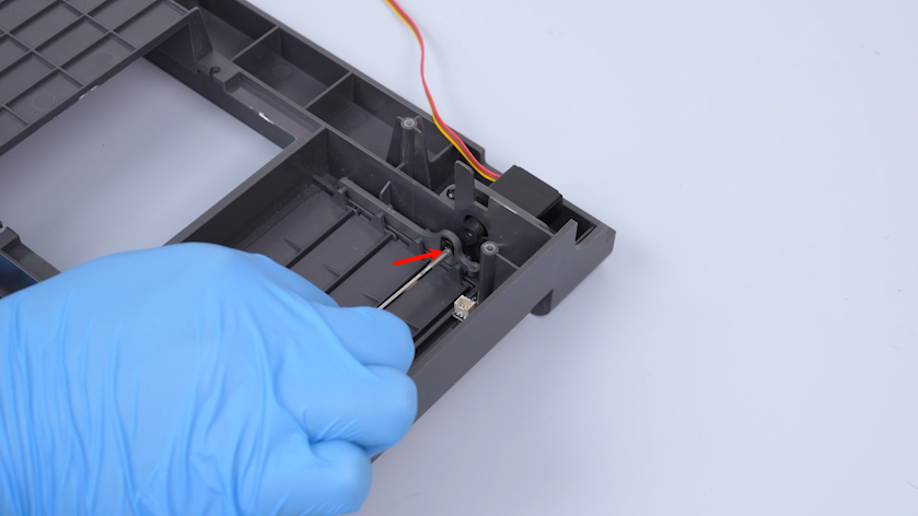
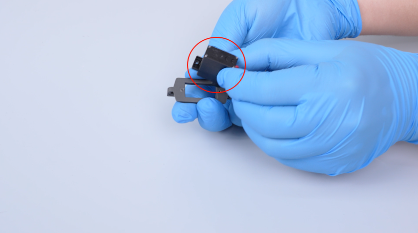
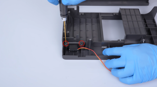
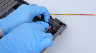
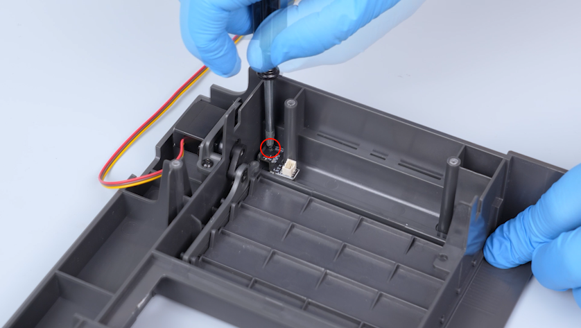
Release and remove the screw securing the servomotor detection board with a Phillips screwdriver.
-
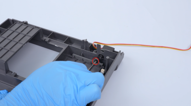
Remove the old servomotor detection board.
¶ Install the new servomotor detection board
-
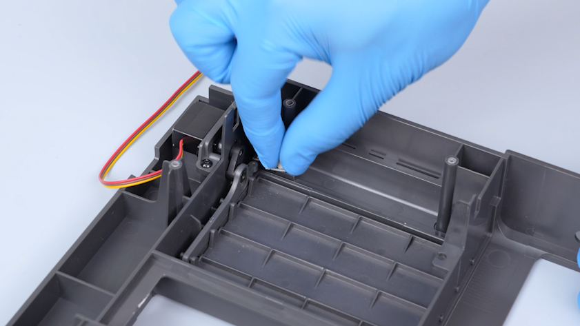
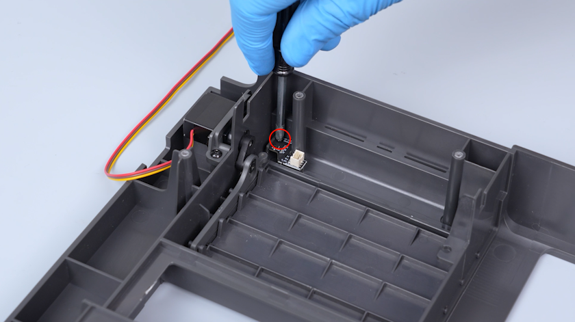
Put the new servomotor detection board in the installation position.
-
Tighten the screw.
¶ Install the left-side cover and the partition
-
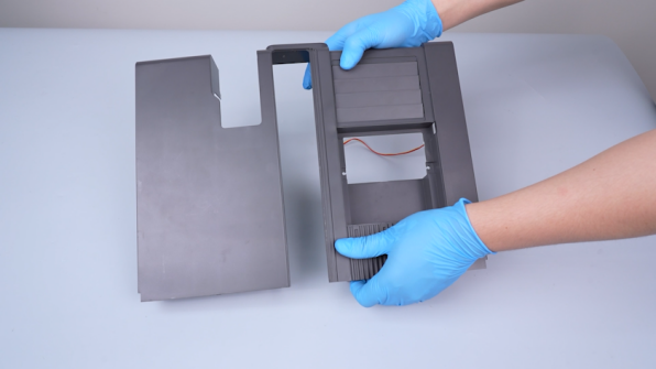
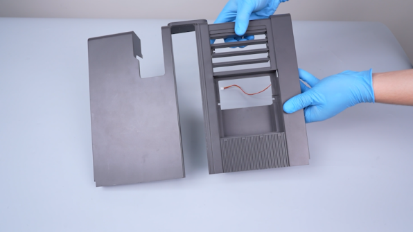
Turn the partition over and open the gratings.
-
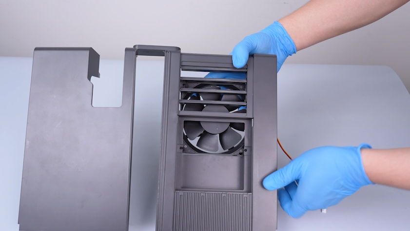
Put the chamber cooling fan in the installation position.
-
Put the fan mounting snaps in the installation positions.

-
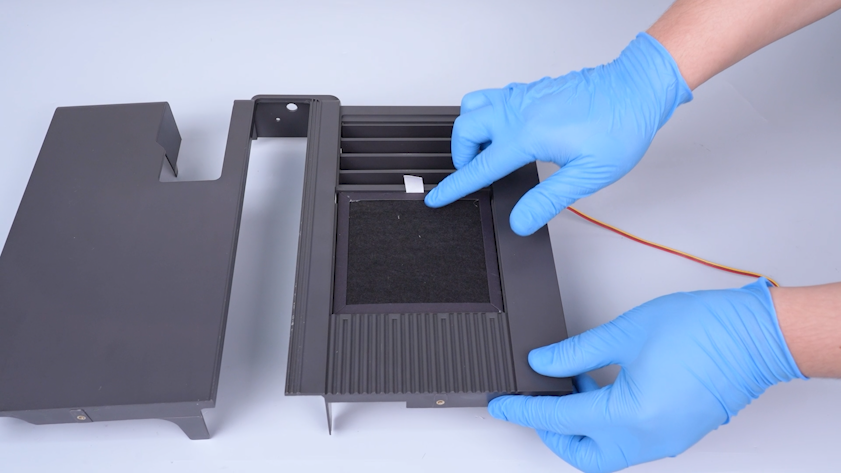
Put the filter in the installation position.
-
Put the grating cover in the installation position.
-
Secure the servomotor cable and the chamber cooling fan with a cable tie. Cut off the excess parts of the cable ties.
-
Put the partition in the installation position.
-
Pull the Z-axis timing belt to raise the heated bed to the middle of the printer.
-
Put the left-side cover in the installation position.
-
Tighten the two screws on the back side of the left-side cover.
-
Tighten the three screws on the upper side of the left-side cover.
-
Tighten the three screws on the front side and bottom of the left-side cover.
¶ Install the back cover and bottom cover
-
Plug in the chamber cooling fan cable and the servomotor cable.
-
Plug in the auxiliary cooling fan cable.
-
Tighten the screw securing the upper part of the partition.
-
Tighten the six screws securing the back side of the partition.
-
Tighten the two screws securing the bottom of the partition.
-
Put the bottom cover in the installation position. Tighten the ten screws securing the bottom cover.
-
Put the back cover in the installation position. Tighten the two screws securing the adapter cable of the CANVAS with a 2.0 mm Allen key.
-
Put the CANVAS extension cable into the gap on the chamber cooling fan side. Put the back cover in the installation position.
-
Tighten the sixteen screws.
Note: Screws labeled by the red circle are M3 x 4. Screws labeled by the yellow circle are M3 x 8.
-
Plug in the communication cable of the CANVAS.
¶ Verification
-
Plug in the power supply cable. Turn the power switch ON (symbol "|") .
-
Confirm that the gratings can be controlled to open and the printer is ready for use.