¶ Tools and Materials
-
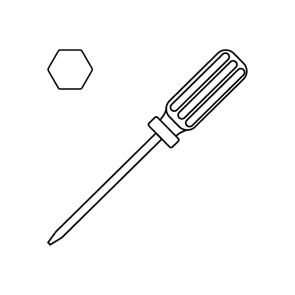
A 2.5 mm Allen key
-
A 2.0 mm Allen key
-
A 1.5 mm Allen key
-
A new tool head board
¶ Tutorial Video
https://www.youtube.com/watch?v=0XCBpwRAjXE
¶ Instruction
¶ Preparation
Turn the power switch OFF (symbol "〇") and unplug the power supply cable.
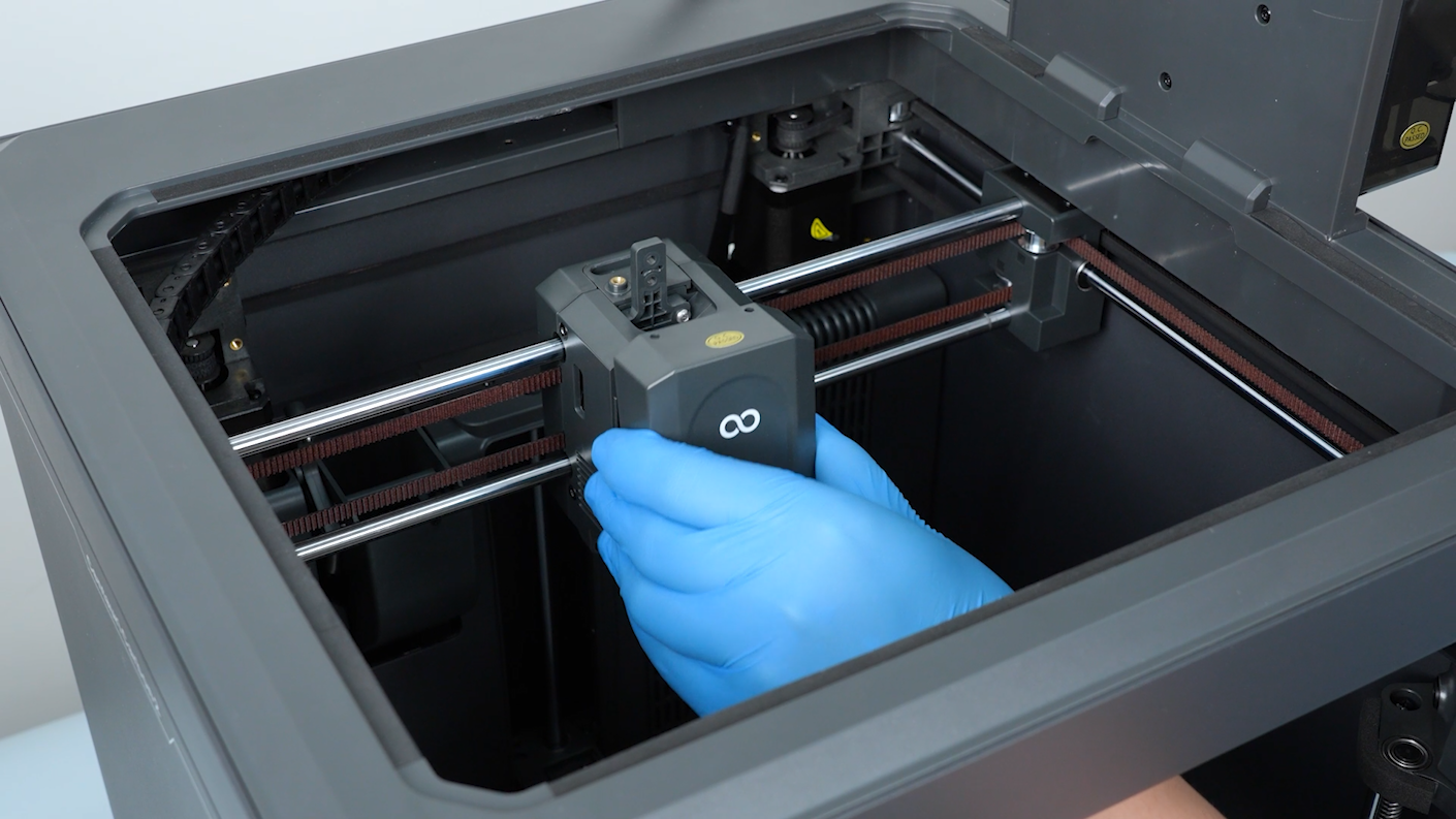
¶ Remove the old tool head board
-
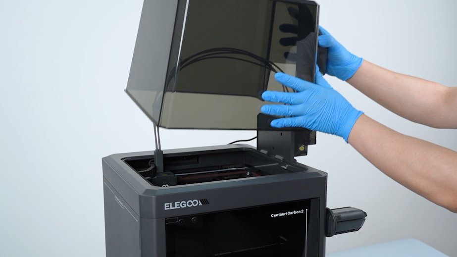
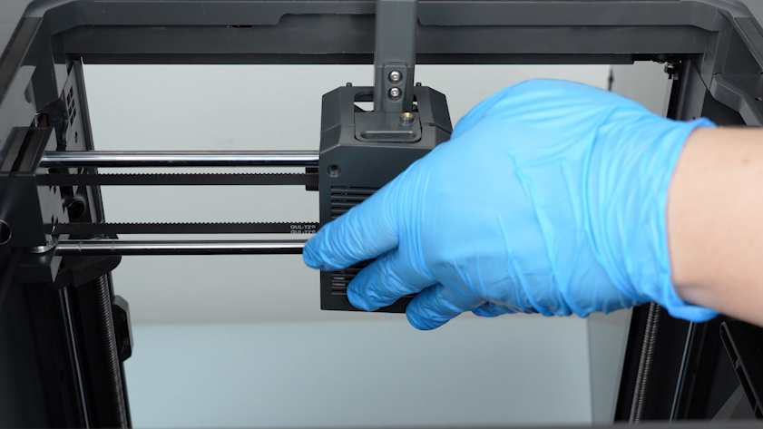
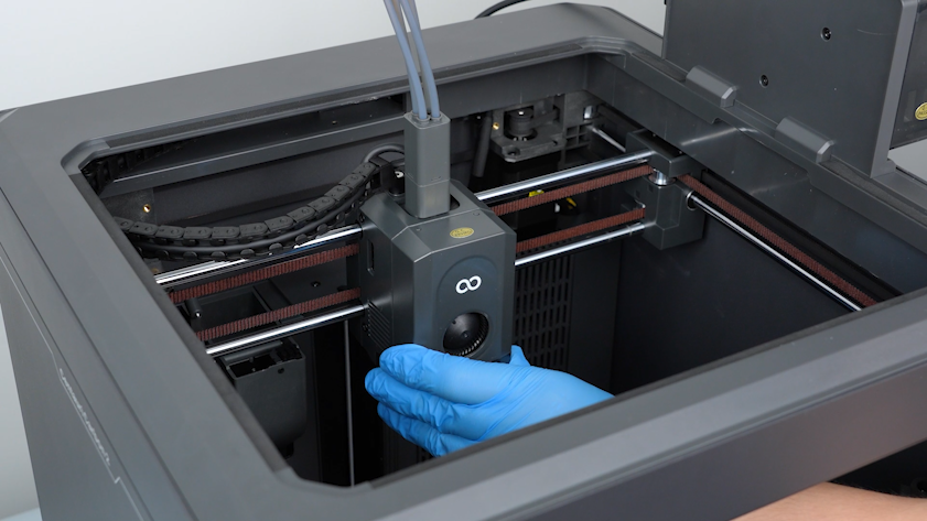
Remove the lid.
-
Open the front cover of the tool head. Unplug the cable of the model cooling fan. Remove the front cover of the tool head.
-
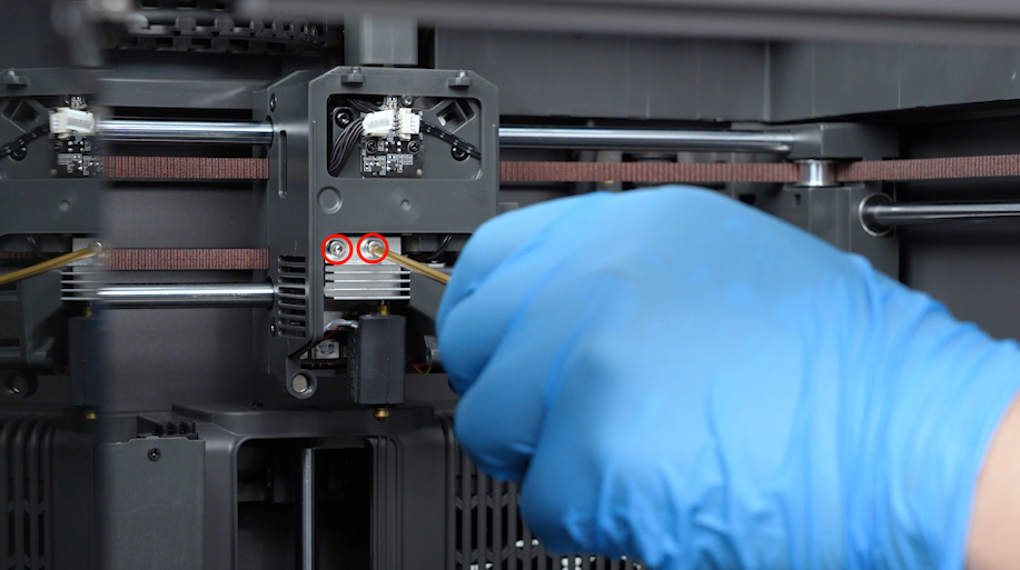
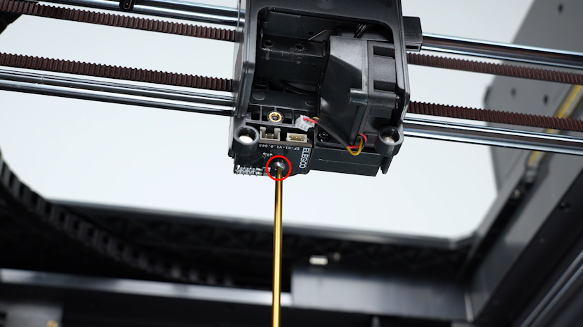
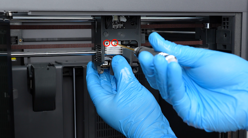
Loosen the screws securing the hotend with a 2.5mm Allen key. Remove the screws with a pair of tweezers.
-
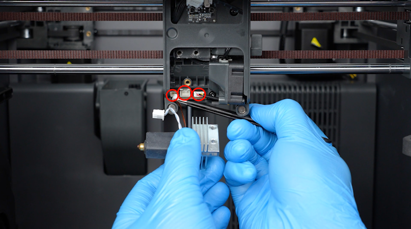
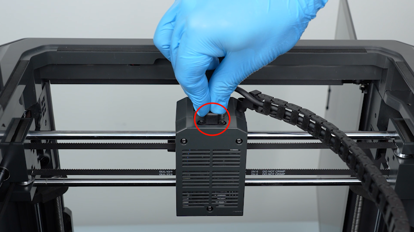
Remove the plugs with a pair of tweezers.
-
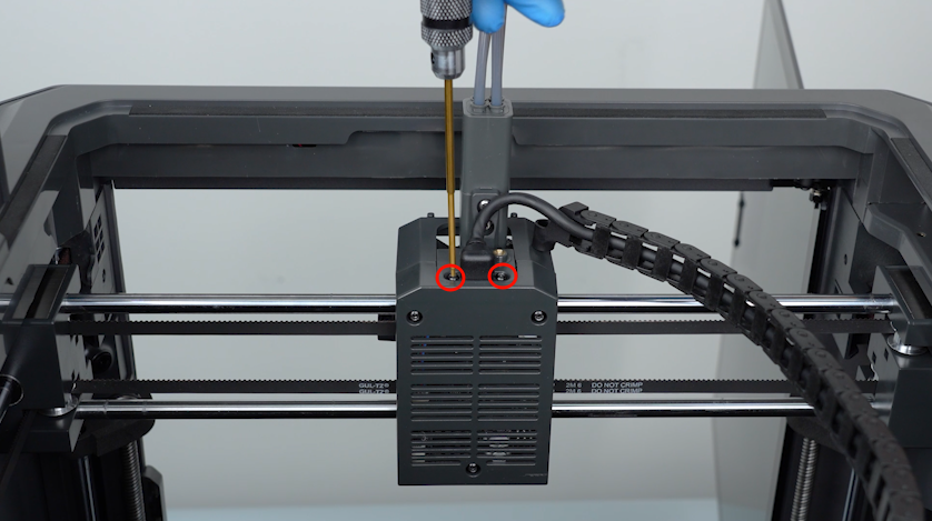
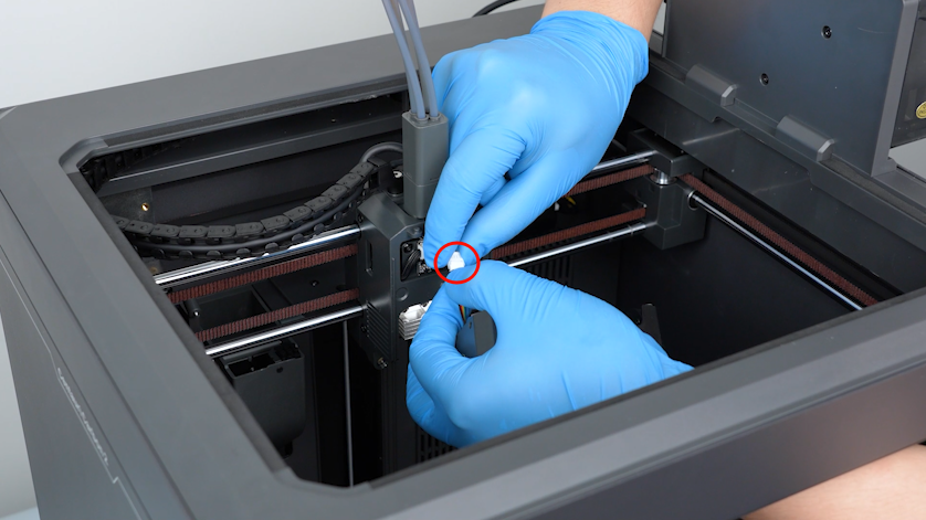
Loosen the two screws securing the extruder communication cable with a 1.5 mm Allen key. Remove the screws with a pair of tweezers.
-
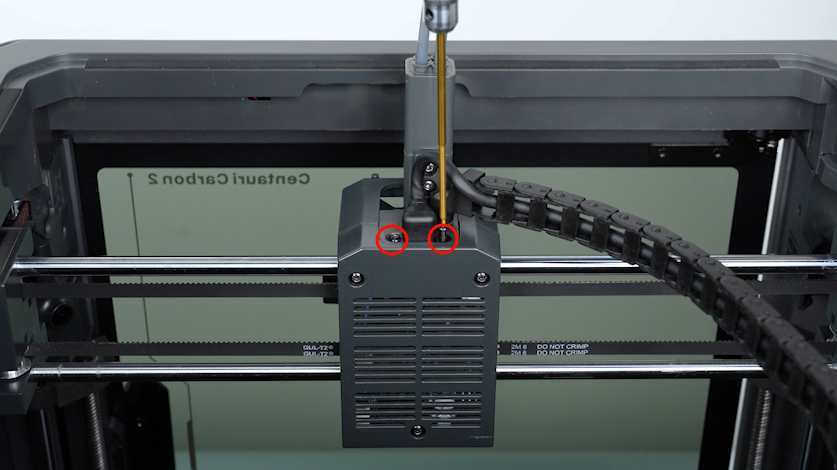
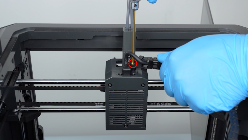
Loosen the screws securing the tank chain with a 2.5mm Allen key. Remove the screws with a pair of tweezers.
-
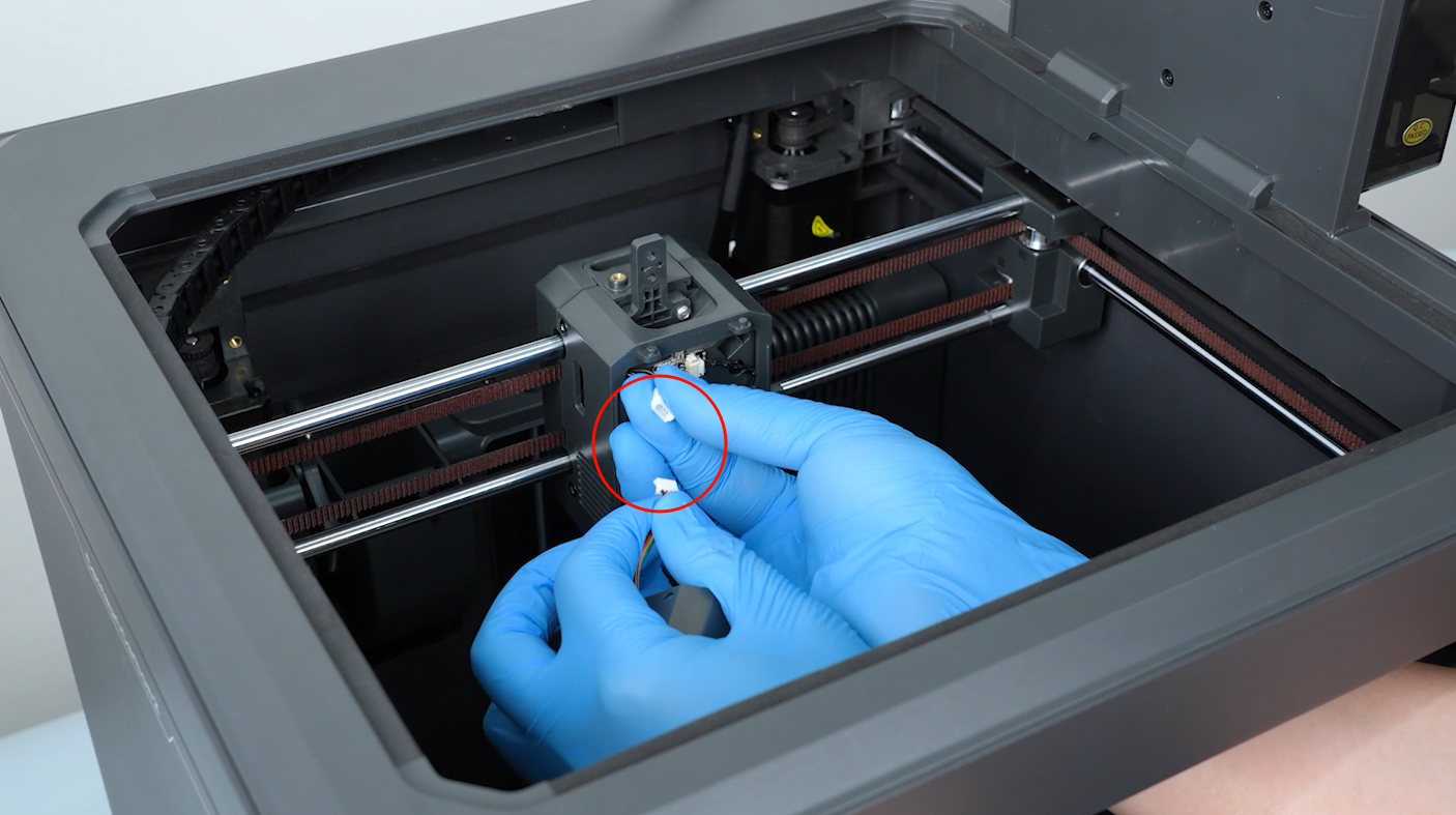
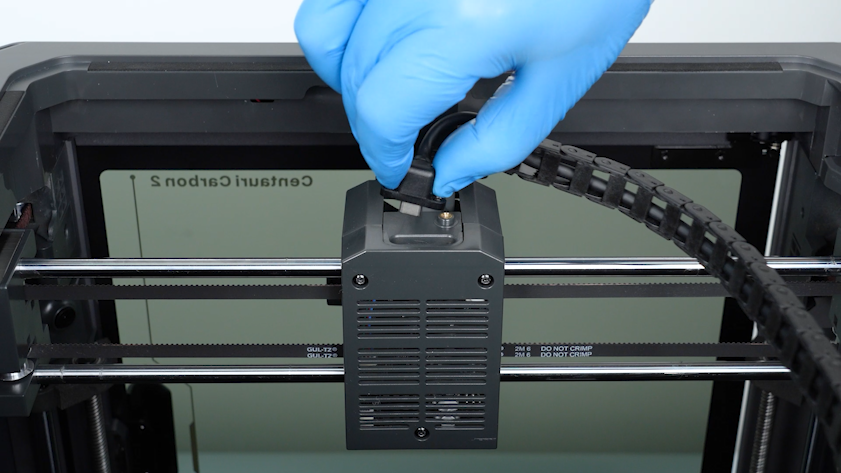
Unplug the extruder communication cable.
-
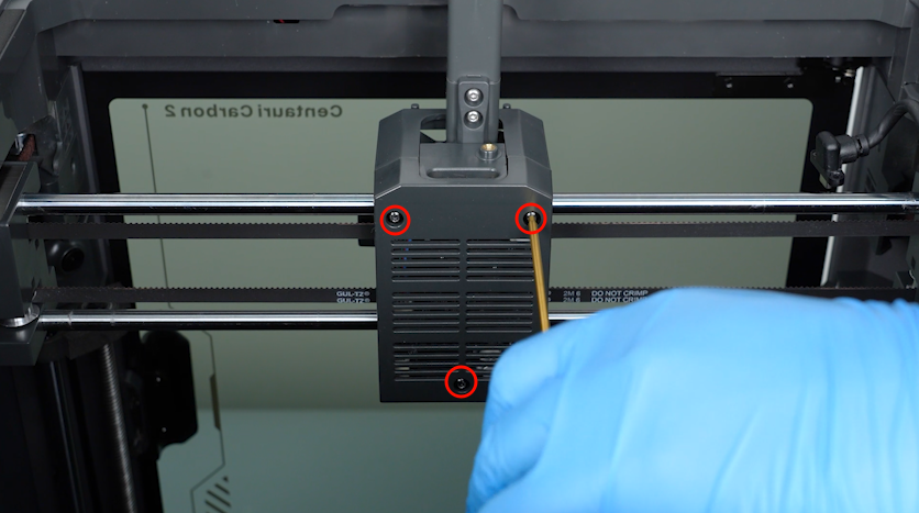
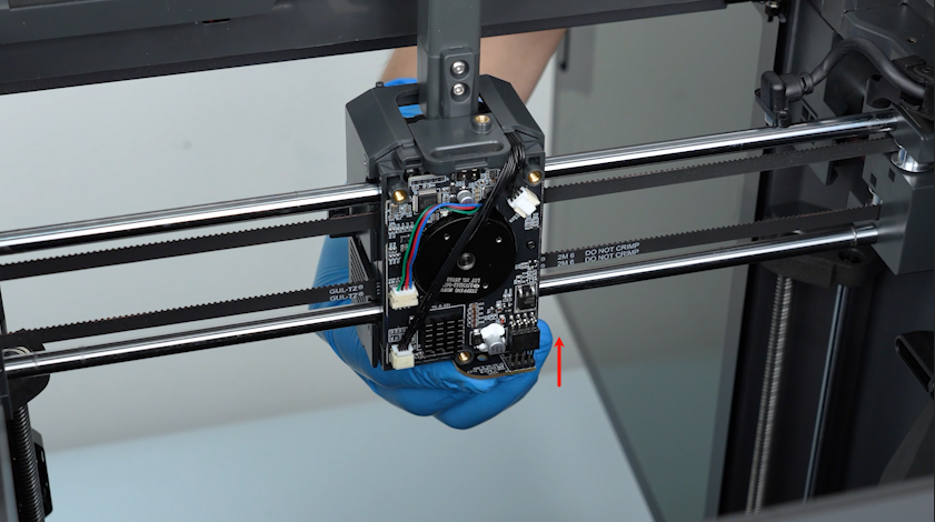
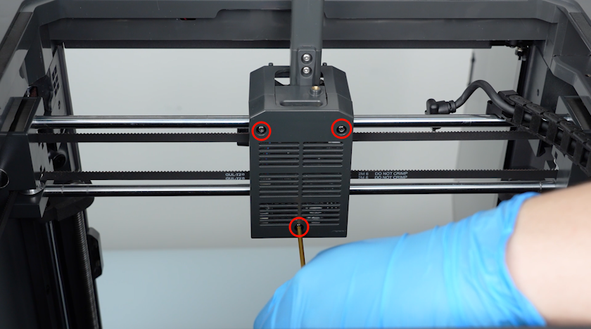
Release and remove the three screws securing the back cover of the tool head with a 2.0 mm Allen key.
-
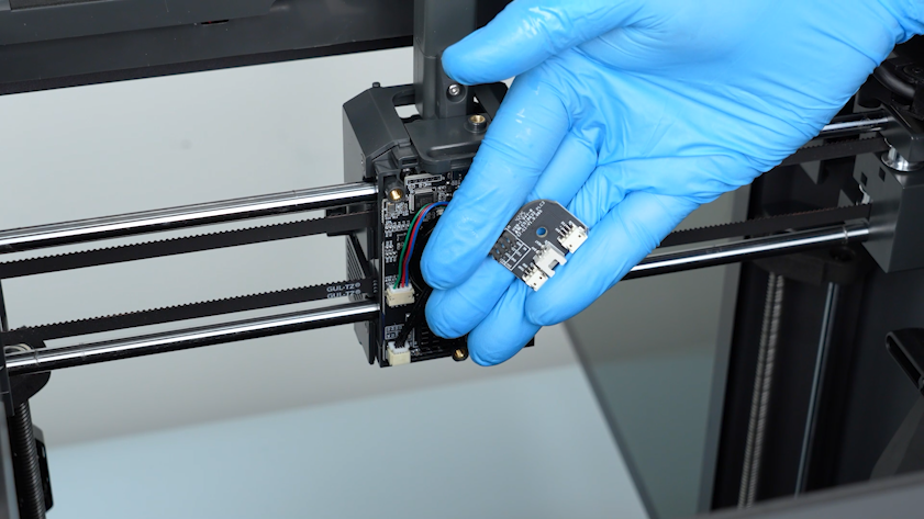
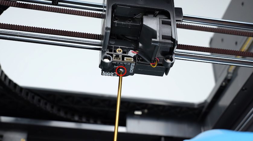
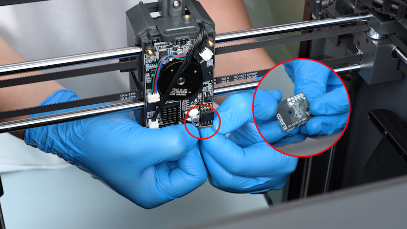
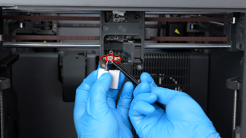
Release and remove the screws securing the tool head board with a 2.0 mm Allen key. Remove the tool head board.
¶ Install the new tool head board
-
Prepare the new tool head board and put it in the installation position.
-
Tighten the screws securing the tool head board.
-
Put the back cover of tool head board in the installation position. Tighten the three screws securing the back cover.
-
Plug in the extruder communication cable.
-
Tighten the two screws securing the extruder communication cable with a 1.5 mm Allen key.
-
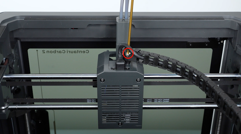
Put the tank chain in the installation position. Tighten the screw securing the tank chain.
-
Insert the plugs with a pair of tweezers.
-
Put the hotend in the installation position and tighten the two screws.
-
Plug in the cable of the motherboard cooling fan. Install the front cover of the tool head.
¶ Verification
-
Plug in the power supply cable. Turn the power switch ON (symbol "|") .
-
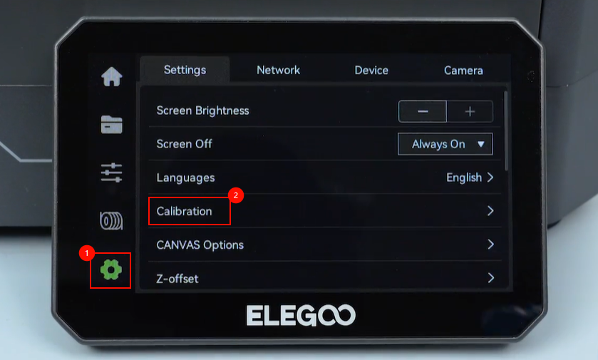
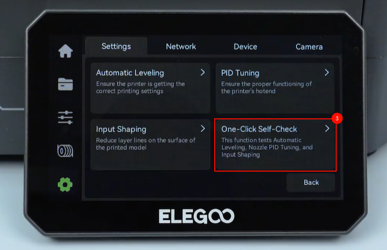
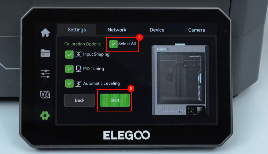
On the touch screen, select Settings - Calibration - One-Click self-check - All - Start. The printer is ready for use after the self-check.